In this article, we’ll look at how to read and convert the raw voltage values into g forces in Arduino accelerometer projects.
Accelerometers are pretty typical in smartphones today, and besides enabling your device to know which way is up, the component can introduce other critical features.
But the primary function you have to achieve first is to get the readings and convert them into usable data to run the other features. Here’s how to do that.
Table of Contents
- What Is an Accelerometer?
- How To Wire an Accelerometer to an Arduino Board
- How To Read Data from the Accelerometer
- Possible Project Expansion
- Wrap Up
What Is an Accelerometer?
Accelerometers are devices used to measure acceleration forces or the rate of velocity changes in an object.
The electrical devices measure these forces in meters/square second (m/s2) or g (G-forces).
G-force is the per unit mass caused by gravity on the earth’s surface, and one g is equivalent to 9.8m/s2.
In electronics, accelerometers are ideal for measuring vibrations and device orientation.
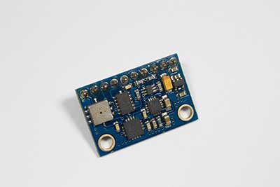
The most typical accelerator module used in electronics projects is the ADXL335.
Based on the 3-axis analog accelerometer IC, the module gives the acceleration in the X, Y, and Z directions as analog voltages statically or dynamically.
Statically measuring the acceleration caused by gravity enables the module to determine and measure tilting.
And sensing dynamic acceleration allows the module to calculate the direction the device is moving.
A triple-axis accelerometer that is ideal for Arduino projects.
These two properties unlock multiple possibilities, and you can incorporate them into your Arduino projects to develop velocity monitors, musical instruments, wearables, etc.
How To Wire an Accelerometer to an Arduino Board
You need the following components to interface the accelerometer sensor module to Arduino.
- Arduino board (Arduino UNO board for this project)
- Accelerometer-ADXL335
- Breadboard
- Jumper wires
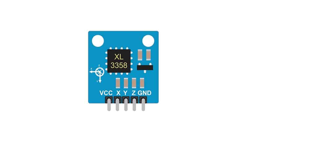
ADXL335 3-Axis Accelerometer Pinout
This accelerometer has six pins.
| Pin | Function |
| Vcc | Power supply for the module |
| X-out | Outputs an analog voltage matching the X-axis acceleration |
| Y-out | Outputs an analog voltage matching the Y-axis acceleration |
| Z-out | Outputs an analog voltage matching the Z-axis acceleration |
| GND | Ground pin for ground connection |
| ST (Self-Test) | Controls the module’s self-test feature |
The self-test feature allows the board to test the module’s functionality in its final application.
When connected to a 3.3V power source, this pin exerts an internal electrostatic force on the accelerometer’s beam.
This force moves the vibrating MEMS beam, enabling you to determine if the device functions as required.
If operating normally, the module should output these values.
- X-axis: -325mV (-1.08g)
- Y-axis: +325mV (+1.08g)
- Z-axis: +550mV (+1.83g)
When operating the accelerometer module, you can ground this pin or leave it open.
But ensure you don’t expose it to voltages exceeding 3.6V to avoid permanent damage.
Pin Connections Between Arduino UNO and ADXL335
It is worth noting that the accelerometer sensor module operates on 1.8-3.6V DC (usually 3.3V) but features an onboard voltage regulator to enable seamless interfacing with 5V microcontrollers, such as the Arduino UNO.
So make the microcontroller-accelerometer connections as follows.
| Arduino UNO | ADXL335 |
| 5V | Vcc |
| A0 | X-out |
| A1 | Y-out |
| A2 | Z-out |
| GND | GND |
Also, ensure you connect the Arduino’s AREF and 3.3V pins to change the board’s analog reference voltage for better accuracy.
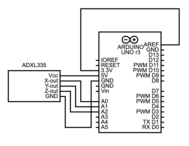
A circuit diagram of the connection between the ADXL335 accelerometer and Arduino UNO
How To Read Data from the Accelerometer
We’ll write code on the Arduino IDE to display the ADXL335 accelerometer sensor’s output on a serial interface.
Code


Code Explanation
Before diving into the code explanation, let’s analyze the accelerometer’s measurement range and ratiometric output.
Measurement Range
The module’s sensing range is +/-3g. So if accelerated to 4g, the accelerometer output might rail.
But the sensor won’t fail or get damaged.
The maximum it can handle is 10,000g before experiencing failure, which is way more than the human body can handle.
So you don’t have to worry about this issue.
Ratiometric Output
As for its sensitivity/ratiometric output, the board’s variable voltage output increases linearly across the range.
So a 0g accelerometer reading (middle of the -3g to +3g range) maps to 1.65V (half of the 3.3V) power supply voltage.
Similarly, 0V translates to -3g, while 3.3V maps to +3g.
Code
So, looking at the code, we begin by declaring the pins through which the accelerometer data will pass to get to the Arduino board (via its analog input pins).
Arduino has a 10-bit ADC, implying 0-1023 integer values (2^10=1024).
So we define the minimum and maximum values to enable the microcontroller to map the 0-3.3V output from the accelerometer into these values.
Next, the sample size variable tells the Arduino to take several samples for each conversion to increase accuracy.
Ten is a good number.
In the Void Setup() function, we first set Analog Reference to external to avoid shorting the active reference voltage generated internally and the AREF pin.
Remember, we connected these two pins to create a reference voltage for accuracy enhancement.
Failure to call and set the Analog Reference function can damage the microcontroller board.
After that, initiate the serial communications with the PC by setting the baud rate to 9600.
In the Void Loop function, the Arduino board reads analog voltage outputs from the accelerometer every 200ms.
We use ReadAxis() instead of analogRead() because it takes the ten ADC accelerometer values and gives the average.
Output Conversion to Acceleration
After reading the voltage from each axis, the next step is to convert the data into g-force or acceleration, and the ratiometric output comes into play.
The map() function handles this process by mapping -3000 to the minimum value (0V), +3000 to the maximum value (3.3V), and the other values in between.
The -3000 and +3000 values represent the measurement range of the ADXL335 (+/-3g).
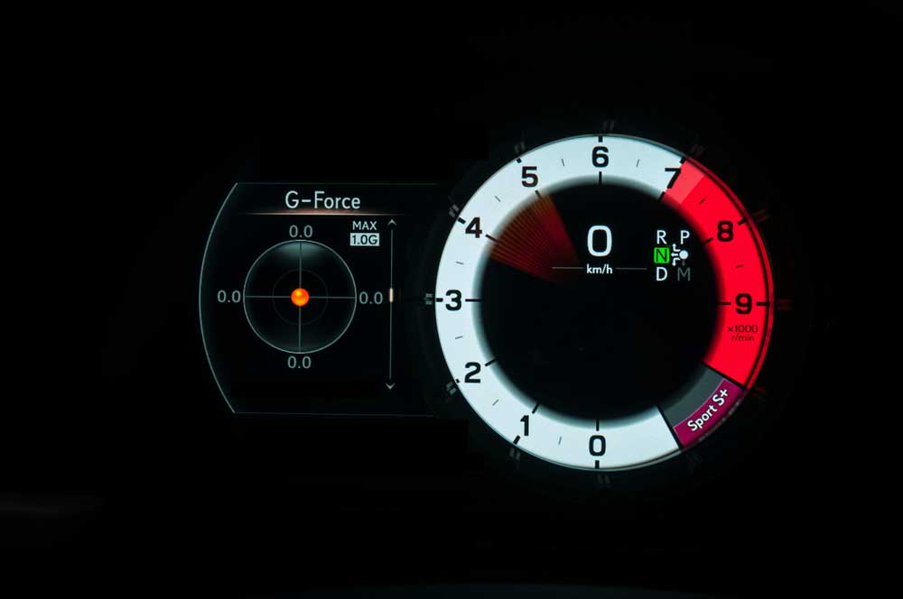
G-force measurements on a sports car’s dashboard
So if yRaw=0 (accelerometer output is 0V on the Y axis), the map function will return -3000.
If the sensor’s variable voltage output is 1.65V, yRaw will be equivalent to 511, and the map function will return 0, while 3.3V will map to 1023.
In this case, the map function will return 3000.
The next step is to convert the raw values to fractional Gs by dividing the values by 1000, then display the results on the serial monitor.
Possible Project Expansion
Once you get this basic Arduino project working, you can expand the system to build a pedometer that counts the number of steps.
You will need an LCD I2C module, a 16*2 LCD, and a battery to make the pedometer portable.
Also, you might have to switch the UNO for a Nano, which is more compact and breadboard friendly.

A wearable pedometer
Wrap Up
As you can see, reading and converting the raw voltage values from accelerometers using Arduino is not challenging.
And once you get this data, you can use this simple sensor to build several projects that require vibration measurement and orientation checking.
So get this code into your project, then be creative.
And contact us if you encounter any challenges. We’ll be happy to help.