If you’re looking for ways to spice up the outlook of your exterior space during the festive season, then this Arduino Christmas light control guide is tailor-made for you.
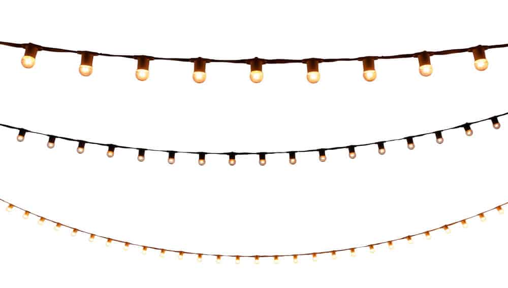
You’ve probably seen the beautiful lights that people place outside their homes during Christmas.
Also, they often make some musical tones as they blink.
We intend to make these showcase lights using easy-to-assemble and cheap electronic components.
We’ll also illustrate how you can control these lights from your wireless network.
Table of Contents
- Components Required
- Power your Buck Converter
- Connect the Power Cord
- Adjust Buck Converter Voltage
- Connect Your Buck Converter to Arduino
- Attach Network Board to the Arduino
- Customize Extension Cables for the Christmas Lights
- Attach Light Strings to an Extension cable
- Link Your Arduino to Extension Cable
- Install Arduino IDE and Light-Controller Sketch
- Find the IPv4 Address
- Test the Lights
- Summary
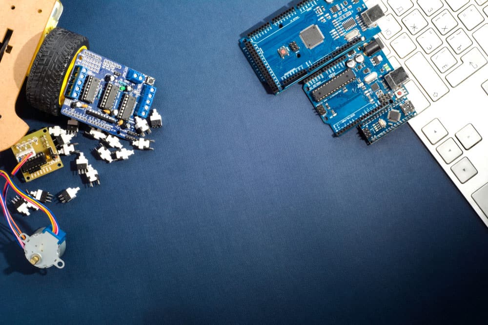
Components Required
Below are some of the key parts you require to get started.
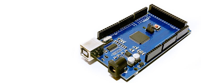
Arduino Mega 2560
Your light controller will not function without this microcontroller.
There are different Arduino versions.
Hence in addition to this board, you can use either:
- Arduino Uno
- Arduino Nano.
Arduino network board
By interfacing it with your computer, the module allows you to create and send animations you want the lights to display.
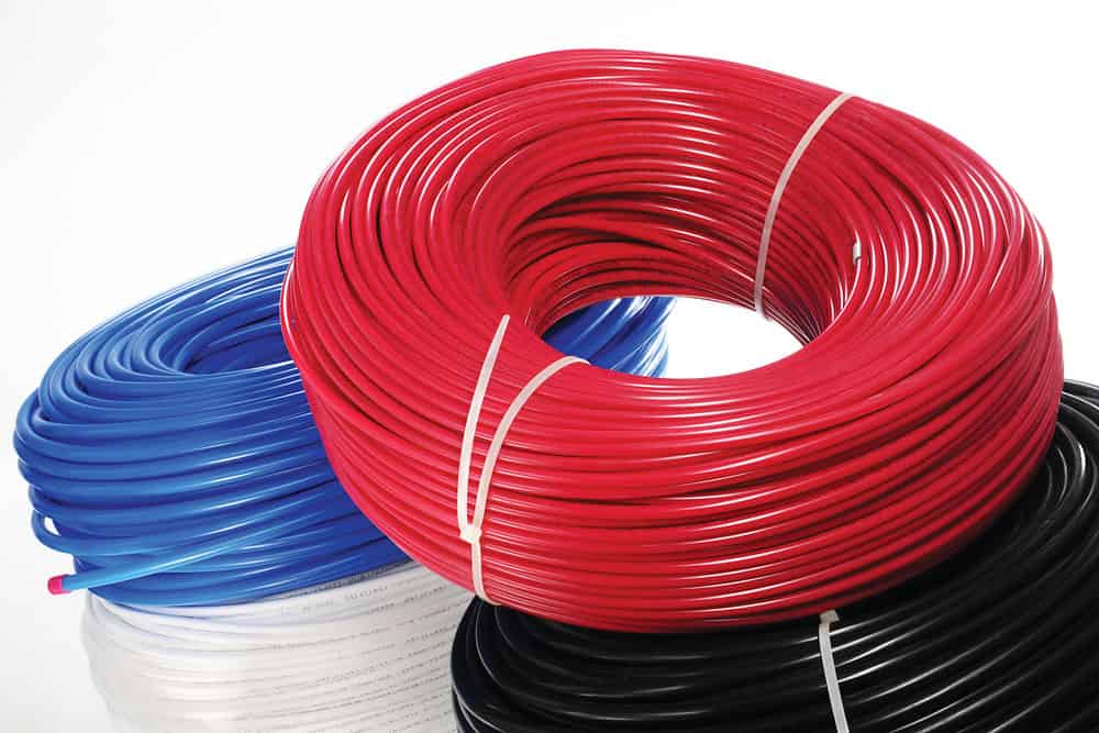
Bunch of Jumper Wires
We need two main types of jumper wires:
- Male-to-female– Interface the Arduino microcontroller with the Arduino network board.
- Male-to-male green jumper wire – link the Arduino microcontroller with the buck converter.
Ws2811 Lights
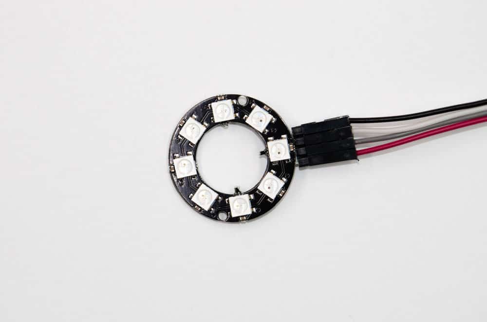
WS2812B, a strand of LEDs with wires.
These special kinds of lights enable you to display various types of animations.
We recommend the Ws2811 lights, but you can also opt for ws2812 Bi-Color LEDs as they are equally effective.
12V External power supply & Buck Converter
Choose a 12V battery, as it’ll sufficiently supply your Arduino board and the lights with power.
You also need to buy a buck converter.
It is to split the supply voltage to 7V (the ideal power supply for an Arduino board) and still deliver 12V to the bulbs.
“Coro” plastic shapes
These will help you form the shapes you desire for your Christmas lights.
Extension cable and Power Connector
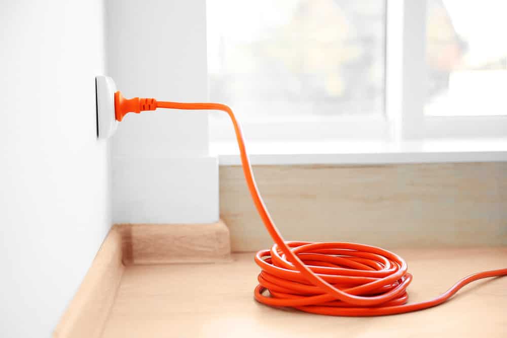
Orange extension into power outlet indoors.
Choose a 3-prong power cable with an 18AWG thickness for the power cable.
Also, buy an ethernet cable, preferably one measuring about 300 feet in length.
Outdoor Enclosure
Lastly, having an enclosure to use your lights outside would be best.
Any glass or transparent plastic box that is waterproof and big enough to hold the lights will fit the billing.
You also need tools such as
- Pliers
- A utility knife
- A wire cutter
- wire splitter
- Heat gun
- Voltmeter
- Screwdriver
- A Soldering gun
- Electrical tape
- A Crimper tool
- Ring crimp-on connectors
- Heat shrink tubing
Power your Buck Converter
Red Wire:
- Using your wire cutter, cut the female part of your male-to-female jumper wire and strip the upper cover to expose the wire inside. Next, attach a connector to the exposed end. This is the end you’ll connect to your power supply’s V+ terminal.
- Connect the other male end of this cable to your buck converter at the “In+” terminal. It would be best if you solder it to ensure it’s permanently connected.
Black Wire:
- Repeat the above process for the black wire. But in this case, you must connect the male end to the “In-” terminal and the female end to the power supply’s V- terminal.
Connect the Power Cord
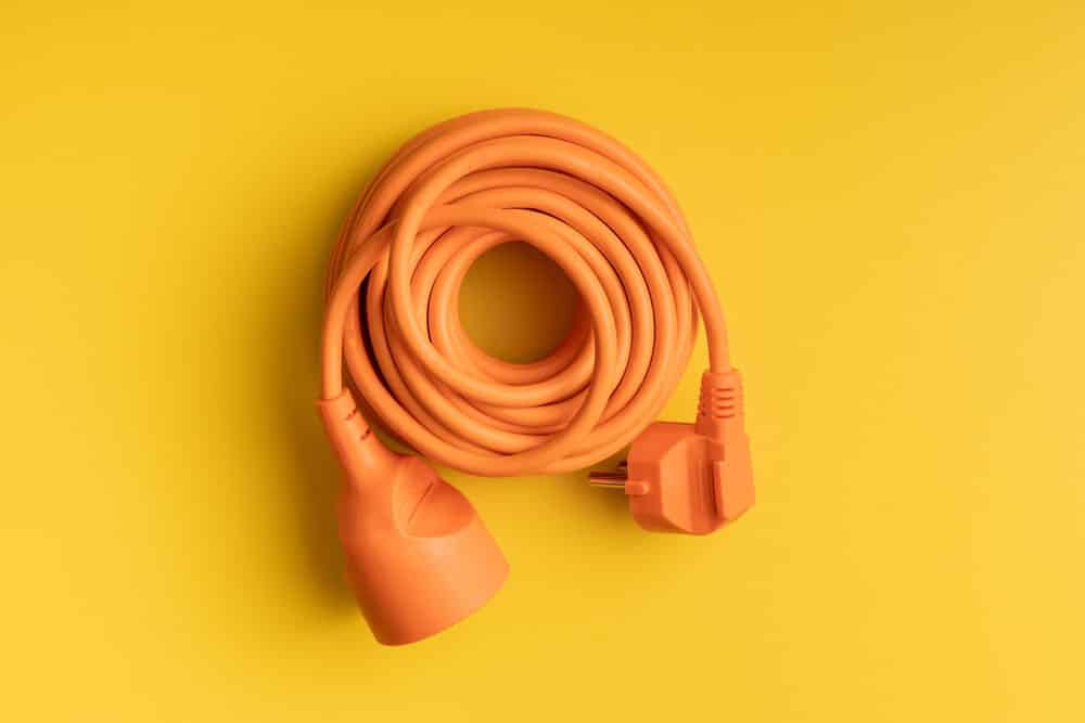
An Orange power cord.
Note that wrong connections can be detrimental, so you must take extra precautions at this step.
The rule of thumb is that you must not plug in the power cord to the power supply until you’re sure the connections are okay.
- Using the wire splitter, peel the cover of your power cord to reveal the three differently colored wires. At this step, ensure you peel it cautiously to avoid removing the covers of the three wires, as this could cause shortcircuiting.
- Next, tightly plug-in connectors to each of the three wires.
- Starting with the neutral wire (it could be blue or white), connect it to the N-terminal of your power supply.
- Next, connect the positive terminal (Brown or black) to the L-terminal.
- Finally, connect the remaining wire (Often green-colored in most wires) to the power supply’s ground wire port.
- Now you can connect the power cord to your wall outlet, but you must primarily confirm that you have correctly connected each of the three wires at the right terminals.
- Next, connect a voltmeter to the positive and negative terminals of the power cord to measure the power. It should read approximately 12V.
Caution: Do not connect wires with a thickness of less than 18 AWG to the power supply, as wires will likely burn out.
Adjust Buck Converter Voltage
We want our buck converter to reduce the power supply voltage from 12V to 7V, which is ideal for our Arduino.
Red Wire:
Connect one end of your male-to-male jumper wire to the buck converter’s “Out+” terminal.
Also, selling it in place for a permanent connection would be best.
Black Wire:
Plug in one end of the black male-to-male jumper wire on the buck converter’s “Out-” terminal and similarly solder it permanently.
Now it’s time to adjust the voltage of the wires connected to the buck converter.
- First, attach a voltmeter to the wire ends, then switch on the power supply.
- Next, rotate the brass screw on the buck converter to set up the voltage reading on the voltmeter at 7V.
Connect Your Buck Converter to Arduino
An Arduino board in a robotics project.
In the above step, we connected the two wires to the buck converter to measure their output voltage.
Now we need to connect them to the Arduino board, so first, switch off the power supply.
Next, connect the black wire to your Arduino’s GND and the red wire to the Arduino’s “Vin” pin.
Connect the power cord to the wall supply and switch it on to test if sufficient current flows to your Arduino board.
The board will blink if everything in the connections is okay.
Attach Network Board to the Arduino
Now we need to connect the network board to the Arduino to facilitate communication of your laptop with the Arduino board via your home WiFi.
Using your male-to-female jumper wires, make connections as per the table below.
| Arduino Network Board | Arduino Pin |
| S0 | 50 |
| ST | 51 |
| SCK | 52 |
| CS | 53 |
| 5V | 5V |
| GND | GND |
During connections, the male end of your jumper wire should be on the network board, while the female end is on the Arduino board.
Next, test if your network board works by connecting it to WiFi via an ethernet cable.
Customize Extension Cables for the Christmas Lights
Extension cables.
These lights feature three main terminals:
- Ground terminal
- Data terminal
- Power terminal
Don’t use wires on the extension cable directly on your lights to avoid interference with the data cable.
- You need three wires, each connecting to the bulb’s terminals. So on your extension cable, pull the white wires together and connect them to create your ground terminal.
- Next, pull all the other wires together (apart from the green wire) to create the power terminal.
- The remaining green wire will be the data terminal.
- Lastly, you must also pull together the other parts of your ethernet cable.
Next, choose whether you want your lights inside or outside. If inside, connect a JST connector.
Connect the male head on one end and the female head on the other.
But if you want it outside, connect male and female 3-pin round outdoor fork connectors on either end.
When connecting to either of these cables, the red wire connects to the ethernet cables’ power terminal and the black wire to the ground terminal.
Finally, connect the yellow wire to the data terminal.
Attach Light Strings to an Extension cable
The lighting network of String-wired bulbs.
Most ws2811 lights feature JST connectors on either side; hence, connecting them directly to the extension cable is easy, as we already installed the connectors in the above section.
But for outdoor connections, you’ll need to modify your lighting network strings to fit waterproof round connectors suited for outdoor connections.
Link Your Arduino to Extension Cable
We’re on the last step of our experiment setup, which involves interfacing the Arduino to the power supply.
The connections are similar for indoor and outdoor setups, but the connectors are different.
Hence, in either case (indoor and outdoor connection), connect your extension cable’s red wire to the positive power supply terminal.
Next, connect the green terminal to Arduino UNO board pin 29 and the black wire to the negative power supply port.
Install Arduino IDE and Light-Controller Sketch
If your Arduino board is new, you must first install IDE software.
Here’s the Arduino code:


Find the IPv4 Address
The Arduino lights controller communicates via your home network.
But, you primarily need to identify your network’s IP Address which you can easily get from your computer via the following steps.
- Launch the command prompt on your computer and enter this on the command line window: “ipconfig.”
- Neck check out for the IPv4 address from the information that pops up.
- Note down the three numbers of your IPv4 address, then exit the command prompt.

Next, update this information on your Arduino Sketch to enable internet control of the computer and the lights via the home network.
Test the Lights
Now everything is set, and it’s time to test if the light show control system is working.
Connect the lights to your Arduino board and the network board to the router.
Now switch on the external power supply.
If your connection is okay, your lights will turn on and display colorful patterns.
If you want them to display different shapes, you only need to control that from your computer.
You can create several animations you want to display, and your lights will showcase them.
Summary
We have dug deep to give you a detailed guide on setting up an Arduino Christmas control project.
Although it looks complex, this is a simple experiment that you can set up in a matter of hours as long as you have all the tools and components in place.
Thanks for reading to the end; you can contact us anytime for more insights and clarifications.