Arduino boards feature a built-in PWM function, and we’ll look at the Arduino PWM frequency to better understand the concept.
The feature relies on a fixed pulse frequency on specific Arduino pins.
And it leaves you to play around with the on/off cycles, allowing you to build diverse projects.
Let’s analyze this development board feature and look at four projects you can build using PWM.
Table of Contents
- What Is PWM?
- Arduino PWM Pins
- How To Change the PWM Frequency of Arduino
- How To Generate PWM Signals Using Arduino
- Arduino PWM Frequency Projects
- Wrap Up
What Is PWM?
Pulse Width Modulation is a signaling technique involving generating voltage pulses at different widths.
Each pulse lasts a specific duration and has a high and low state length depending on the duty cycle.
The PWM frequency determines the pulse duration.
For instance, with a 490 Hz PWM frequency, each pulse will last 1/490 seconds.
But the correct way to specify PWM signals is in duty cycles. The duty cycle value (given as a percentage) determines the duration in which the pulse stays high.
For instance, a 25% duty cycle PWM signal at 490 Hz stays high for (1/490 x 25) seconds. It then goes low for (1/490 x 75) seconds.
On the other hand, a 75% duty cycle PWM signal at the same frequency reverses the duration values.
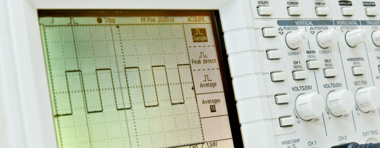
It is vital to note PWM signals are not analog signals.
Some might say the technique uses digital means to generate an analog result, but that is not entirely true.
PWM signals are square waveforms created by digitally switching a voltage signal on and off.
So the waveform has discrete values for the on and off positions, meaning it is not an analog waveform.
Arduino PWM Pins
Each Arduino board has different PWM pins, and here are the ones you can use in these four boards.
| Arduino Board | PWM Pins | PWM Frequency |
| Arduino UNO | 3, 5, 6, 9, 10, and 11 | 490 Hz, but pins 5 and 6 operate at 980 Hz |
| Arduino Mega | 2-13 and 44-46 | 490 Hz, but pins 3 and 11 operate at 980 Hz |
| Arduino Mini | 3, 5, 6, 9, 10, and 11 | 490 Hz, but pins 5 and 6 operate at 980 Hz |
| Arduino Nano | 3, 5, 6, 9, 10, and 11 | 490 Hz, but pins 5 and 6 operate at 980 Hz |
How To Change the PWM Frequency of Arduino
As you can see above, Arduino boards come with pre-set PWM frequencies. But you can adjust these values.
Here’s how the PWM system works.
ATmega168P and 328P microcontrollers have three counter/timer registers, and the speed of these counters determines the PWM signal frequency.
And the counter clock is the result of the system clock (16 MHz) divided by the prescaler value.
This prescaler value contains three bits stored in at least three of the timer register’s three least significant bits. These include:
- CS02, CS01, and CS00 for timer TCCR0B
- CS12, CS11, and CS10 for timer TCCR1B
- CS22, CS21, and CS20 for timer TCCR2B
Since the boards running these microcontrollers have six PWM pins, it implies each counter/prescaler handles a pair.
For instance, timer registers TCCR0B controls pins 5 and 6, which operate at 980 Hz.
On the other hand, counter TCCR1B controls pins 9 and 10, while TCCR2B controls pins 3 and 11.
Remember, the speed of this counter determines the PWM signal frequency.
So each pair will always operate at the same frequency because they have the same controller.
So to change the frequency of each pair, you need to alter the least significant bits of the prescaler value.
This value has eight bits, so we modify the last three in binary format.
It can get a little complicated. But all you need to know is you can change the frequency to as low as 30 Hz.
On the higher side, it can go to over 60 KHz. And you can do all these adjustments using a single line of code.
Let’s use the Arduino UNO as an example.
PWM Pins D5 and D6 (TCCR0B)
By default, D5 and D6 operate at the highest PWM frequency.
But you can alter this frequency using these lines of code.
| Code | PWM Frequency |
| TCCR0B = TCCR0B & B11111000 | B00000001; | 62500 Hz (62.5 KHz) |
| TCCR0B = TCCR0B & B11111000 | B00000010; | 7812.50 Hz (7.8 KHz) |
| TCCR0B = TCCR0B & B11111000 | B00000011; | 976.56 Hz (default PWM frequency) |
| TCCR0B = TCCR0B & B11111000 | B00000100; | 244.14 Hz |
| TCCR0B = TCCR0B & B11111000 | B00000101; | 61.04 Hz |
PWM Pins D9 and D10 (TCCR1B)
| Code | PWM Frequency |
| TCCR1B = TCCR1B & B11111000 | B00000001; | 31372.55 Hz (31 KHz) |
| TCCR1B = TCCR1B & B11111000 | B00000010; | 3921.16 Hz (3.9 KHz) |
| TCCR1B = TCCR1B & B11111000 | B00000011; | 490.2 Hz (default PWM frequency) |
| TCCR1B = TCCR1B & B11111000 | B00000100; | 122.55 Hz |
| TCCR1B = TCCR1B & B11111000 | B00000101; | 30.64 Hz |
PWM Pins D3 and D11 (TCCR2B)
| Code | PWM Frequency |
| TCCR2B = TCCR2B & B11111000 | B00000001; | 31372.55 Hz (31 KHz) |
| TCCR2B = TCCR2B & B11111000 | B00000010; | 3921.16 Hz (3.9 KHz) |
| TCCR2B = TCCR2B & B11111000 | B00000011; | 980.39 Hz |
| TCCR2B = TCCR2B & B11111000 | B00000100; | 490.20 Hz (default PWM frequency) |
| TCCR2B = TCCR2B & B11111000 | B00000101; | 245.10 Hz |
| TCCR2B = TCCR2B & B11111000 | B00000110; | 122.55 Hz |
| TCCR2B = TCCR2B & B11111000 | B00000111; | 30.64 Hz |
But for this code to work, you must type it before initializing the digital pin as an output.
How To Generate PWM Signals Using Arduino
The function for generating a PWM signal is analogWrite(), with the arguments pin and value.
analogWrite(pin, value);
The first argument (pin) is the Arduino pin you want to use to generate the PWM signal. These are the ones in the table above.
Value refers to the duty cycle.
However, we don’t use the percentage (0-100).
This parameter ranges from 0-255, with 0 being 0% or 0V and 255 being 100% or 5V.
Arduino PWM Frequency Projects
Let’s look at some projects using PWM signals to understand this signaling technique.
LED Brightness Control
Have you heard of or used dimming lights before?
The fixtures use PWM to control the power getting to the LEDs.
This modulation creates high LED on/off frequency switching that can alter the brightness by adjusting the duty cycle.
To build this project, you’ll need these components.
- An Arduino Nano board
- A 220R resistor
- Jumper wires
- An LED
Circuit Diagram
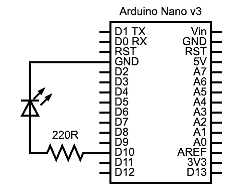
An Arduino PWM LED brightness control project circuit diagram
Code
Open the Arduino IDE and upload the following code.
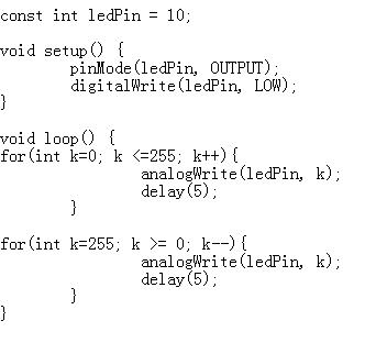
The program sets digital pin ten as an output pin, then writes it to a logic low mode (off).
After that, it sets the LED to begin glowing up to maximum brightness (5V), then back to zero.
Since the void loop function runs continuously, it will keep the FOR loops running from 0 to 255 and back.
But if you think about the example talked about earlier (dimming lights), these fixtures don’t operate that way.
You control the brightness by turning a knob, and this knob is usually a potentiometer.
LED Brightness Control Using a Potentiometer
You’ll need the following components if you want manual control over an LED’s brightness.
- Arduino Nano
- LED
- 10K potentiometer
- 220R resistor
- Jumper wires
Circuit Diagram
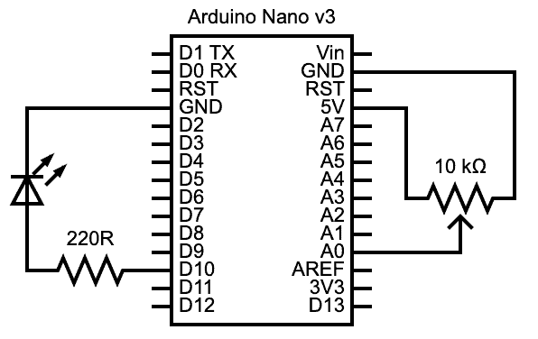
An Arduino PWM LED brightness control (with potentiometer) project circuit diagram
Code
Paste this code in your Arduino IDE editor and upload it to the board.

Instead of switching the LED gradually on/off, this code relies on the potentiometer input via an Arduino analog pin.
First, we set the potPin integer variable to the analog pin A0 to collect the voltage signal from the potentiometer.
And this potPin should be in input mode. The LED pin remains an output like it was earlier.
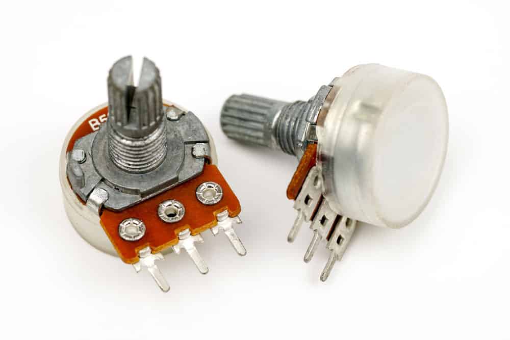
Two potentiometers
In the void loop function, the code converts the analog sensor reading to a digital value between 0-1023 using analogRead().
But we can’t use these values to control the LED’s brightness.
Remember, the duty cycle value in the analogWrite() function ranges from 0-255. So we have to map the digital value (0-1023 to 0-255).
After that, we send the duty cycle to the PWM function (analogWrite) to send the PWM signal to the LED.
This project is similar to the LED dimming lights you would buy to install in your home.
DC Motor Control
Controlling a DC motor is similar to the LED project above.
You’ll need the following components.
- Arduino Nano
- 10K potentiometer
- Small DC motor
- Jumper wires
Circuit Diagram
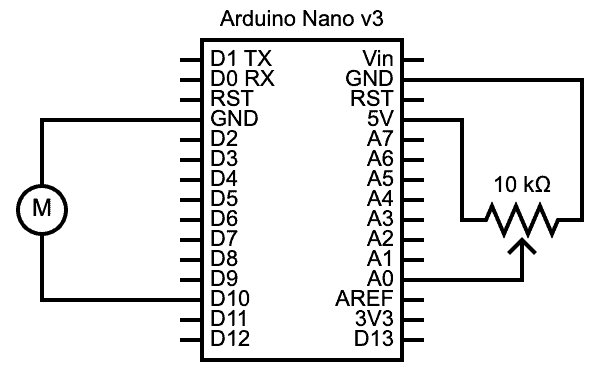
An Arduino PWM tiny DC motor control project circuit diagram
You can power a small current & voltage-rated DC motor directly using an Arduino board’s D10 pin.
For instance, you can use a CD/DVD drive motor.
But higher-rated motors will need extra components, such as a decoupling capacitor, diodes (for protection), and transistors.
Motors requiring more electric current will need DC motor drivers.
Let’s stick to the tiny electric motor to keep the project simple.
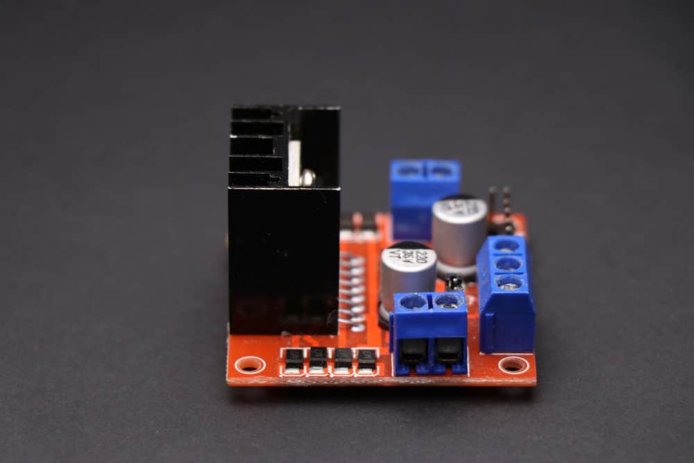
An L298N motor driver
Code

The same logic applied to the LED dimming potentiometer switch above applies to the motor control.
Turning the knob alters the PWM signal going to the motor, which increases or decreases its rotational speed.
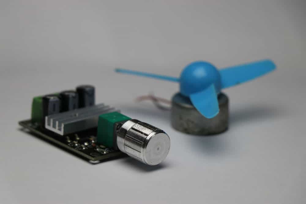
A DC motor PWM controller board with a DVD motor fan
Applications for this project include variable speed fans.
Think of overhead, computer cooling, and table fans.
Sound Control
In this last example, we will control the sound output from a buzzer using a potentiometer.
You’ll need the following components.
- Arduino board (Nano)
- Buzzer
- Potentiometer
- Jumper wires
Circuit Diagram
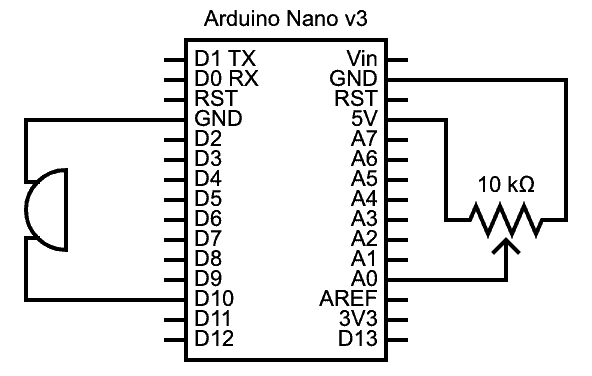
An Arduino PWM sound control (with potentiometer) project circuit diagram
Code

Like the motor control Arduino project above, this code adjusts the power sent to the buzzer.
As you turn the knob, the map function translates the digital values converted using analogRead to numbers between 0 and 255.
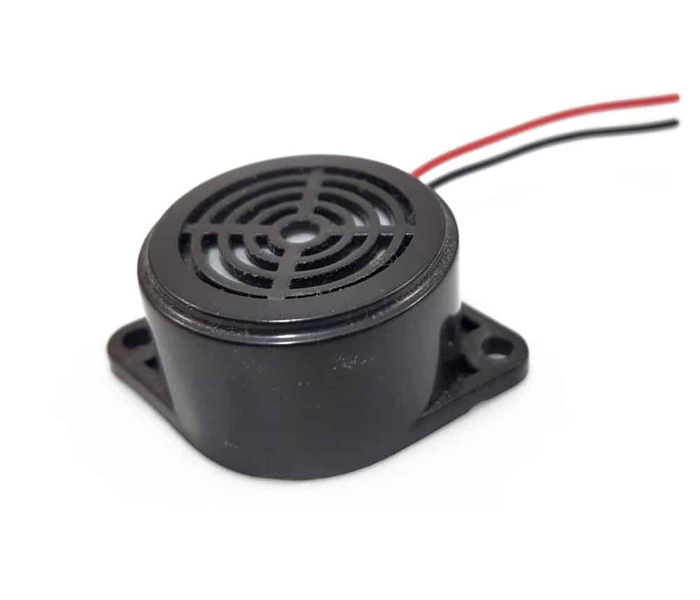
A black buzzer
The Arduino board converts these values to duty cycles, creating a PWM signal in real-time to power the buzzer.
So the buzzer will produce a varying audio signal.
Wrap Up
There you have it! Playing around with the variable duty cycle PWM signal unlocks multiple possibilities, such as the projects above.
And it is vital to note that you can adjust the PWM frequency to suit different applications.
Although such project code is more technical, it is doable, but the adjustment is within a specific range.
So you can research this adjustment and make changes to introduce the appropriate PWM signal into your project.