Building an Arduino security system can be simple or complex, depending on your security requirements.
A basic system can consist of a password-secured or RFID door lock. But complex systems can bring on board the following.
- Flame & gas detectors for fire sensing
- Infrared sensor (motion detector)
- Laser light intrusion detection
But let’s focus on one of the aspects first: laser light intrusion detection.
Once the project becomes operational, you can add the extra features above.
So we’ll look at how you create a laser light security system using Arduino. But first, here are the benefits of building a DIY home security system.
Table of Contents
Why Make a DIY Home Security System
Making a DIY home security system gives these five benefits.
- Total Control: With vendor security systems, the third party will receive the data, then send alerts to your phone. There might be time delays or no alerts if the vendor systems are faulty. So you might not resolve the situation on time. But with a DIY system, there’s no third party. You run everything.
- Low Fees: The operational costs of a DIY home security system are relatively low. You might only have to pay for internet and IoT platform fees. But vendor home security systems have high running costs.
- Zero False Alarm Fees: Some emergency security services charge penalties for false alarms. You don’t have to worry about these with a custom-made system.
- Flexible Installation/Service: Home security system vendors usually charge homeowners for system changes or upgrades. Some even charge for cancellation. But these costs don’t apply to your DIY project. You can make changes at zero or low costs.
- Easy To Move: Most vendor security systems have monitoring centers that should have your address. So you have to inform them when you move and they should do a reinstallation at your new address. But with a DIY system, you handle the installation. Plus, most are compact, portable systems that are easy to move and install.
Laser-Light Security System Project
If you are a big fan of movies, you must have watched one where intruders encounter red lasers protecting valuable assets.
These include precious jewelry or paintings in museums or homes.
Blocking this laser light path triggers alarms automatically and locks all doors.
The system might seem highly advanced, but it is a relatively easy-to-make Arduino project.
You’ll need the following components.
- Arduino UNO board
- KY-008 laser transmitter module
- LDR
- 10K resistor
- Buzzer
- Reset push-button switch
- Jumper wires
- Breadboard
The primary component in the system is the laser diode module KY-008, which has the following properties.
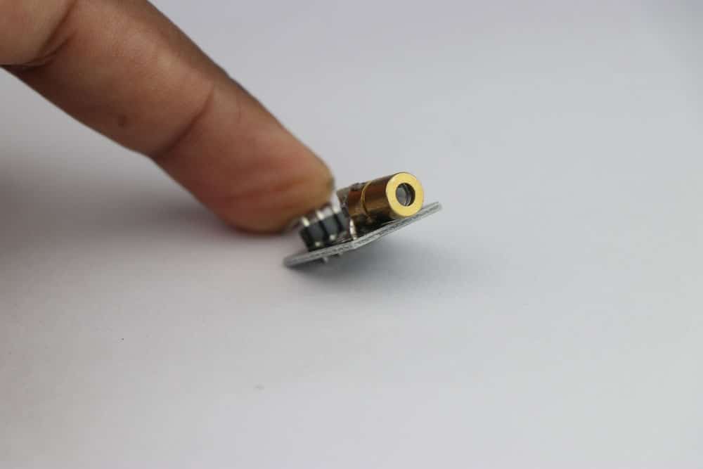
A laser diode module
- Dimensions: 18.5mm x 15mm
- 5V operating voltage
- 5mW output power
- 650 nm wavelength red laser diode
- Less than 40mA operating current
- Operating temperature: -10°C to 40°C
Ensure you handle the laser with caution when turned on. Don’t point the light into your eyes.
This laser cannot handle intrusion detection alone. It needs a sensor on the other end to check for interruptions. The function requires an LDR.
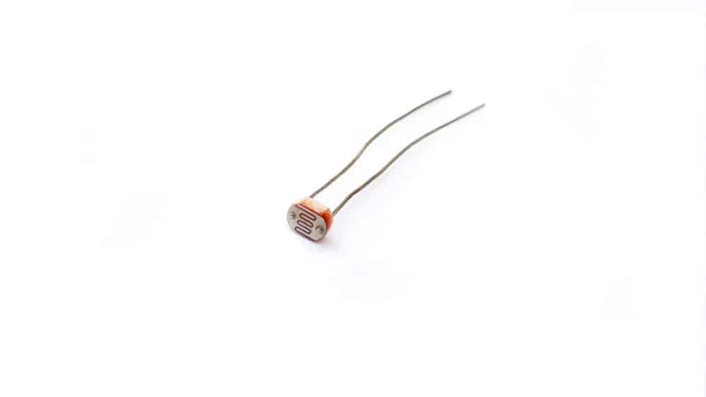
A 2mm light-dependent resistor
Here is the circuit diagram.
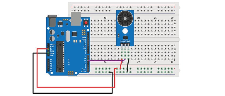
Circuit Diagram
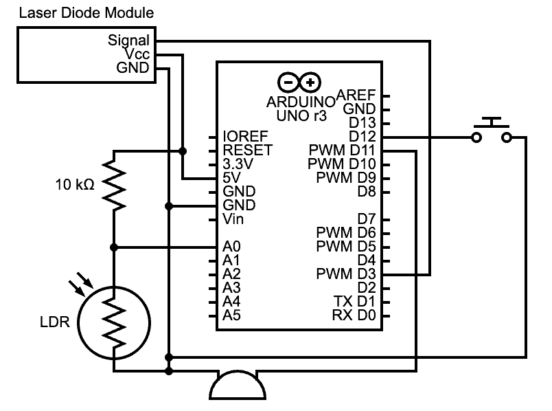
An Arduino laser-light security system circuit diagram
When setting up the system, ensure the laser transmitter module directly points at the LDR.
So as the laser outputs a concentrated beam of light, the light-sensitive LDR captures this light.
And it outputs varying analog voltage values depending on the light intensity.
But this voltage should not exceed a certain threshold if the laser shines light directly at the LDR.
So if an object or intruder blocks the light path, the voltage will exceed the threshold and activate the alarm.
From the circuit diagram above, you’ll note that we haven’t connected the LDR (photoresistor) directly to the board.
Instead, we attached a resistor to the power supply side and got the signal between the two.
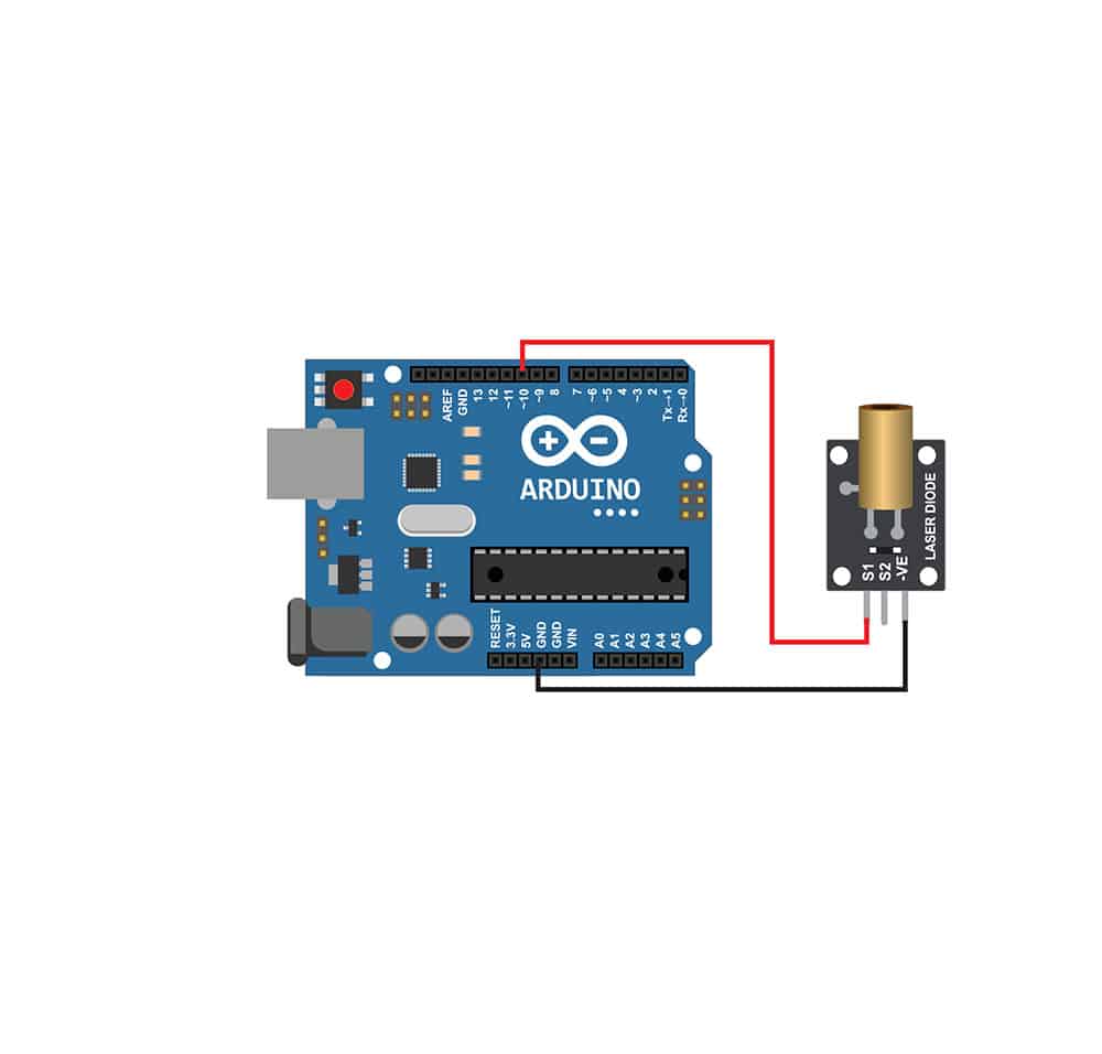
A laser diode module connected to an Arduino board
The LDR has a broad resistance variance, which can go from 1MΩ to 100KΩ.
Such a high impedance limits the current that can flow through (between 5V and analog pin A0).
So the voltage drop will be insignificant, and the board won’t notice them.
It will always be close to 5V.
But adding the resistor creates a voltage divider.
This device varies the voltage significantly depending on the light intensity on the LDR.
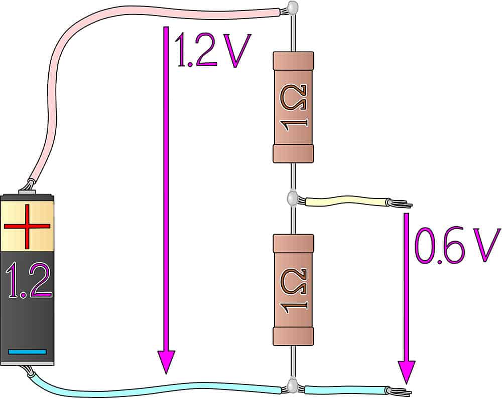
A resistive voltage divider circuit
With that out of the way, here’s how to implement the logic above into code.
Code

Code Explanation
The program begins by declaring the pin variables used to make the hardware connections.
After that, we set the threshold value for the LDR.
If the reading exceeds this value, the code will trigger the alarm.
Next, we set the laser pin (pin 3) as an output to power the red laser light module.
For the button pin, we’ve coded it to detect input using the built-in pull-up resistor.
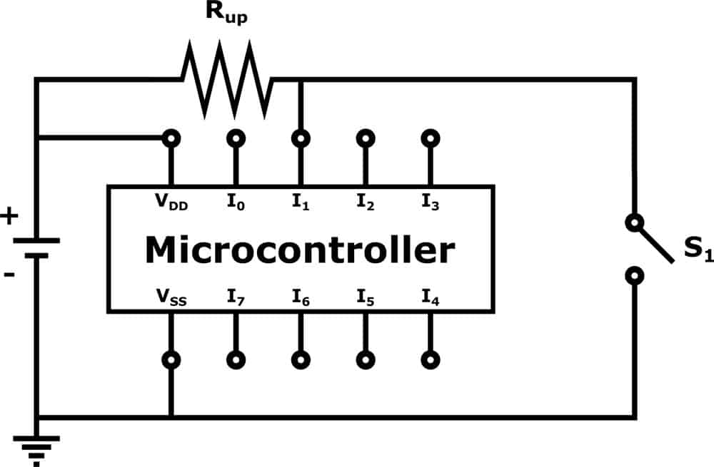
A microcontroller with a pull-up resistor in the circuit to stop floating
This internal resistor has a value of between 20KΩ and 50KΩ.
It ensures the digital pin (connected button) always remains in a high state.
So when you press the button, you complete the circuit and ground the resistor, taking it to a low state.
Since it is a push button, you’ll release it almost immediately, returning the pin to a high state.
The pin mode input_pullup mode ensures you capture the pin’s input if it undergoes this low-to-high state change.
After that, the code initializes communications with the serial monitor to 9600 bits per second.
This communication will help you track the program’s progress and debug errors on your computer.
Next, we define the boolean variable alarm_state to keep track of the alarm’s state. At this point, it is off (false).
Void Loop
This function handles the core logic of the program using an if-else statement.
First, it checks if the alarm is off using this statement (!alarm_state).
If it is off, the code turns on the laser for one second.
It immediately checks the LDR readings to see if it exceeds the threshold set earlier.
If the sensor_value exceeds the threshold, the alarm turns on and sends a PWM pulse to the buzzer.
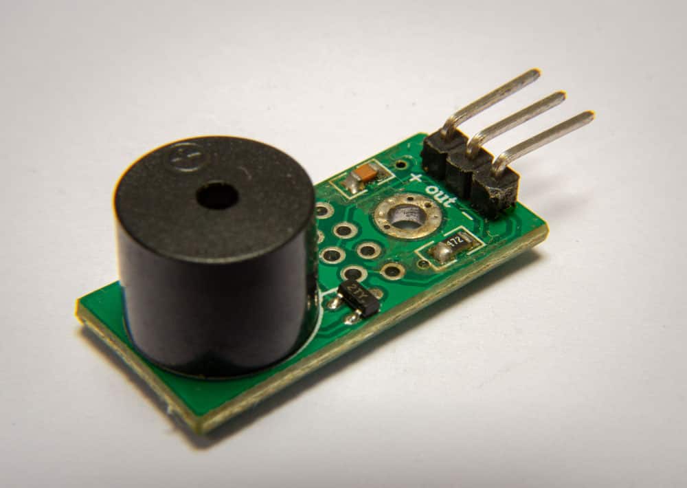
An Arduino piezo buzzer module
This buzzing occurs due to this line.
tone(buzzer_pin, 440);
“Tone” is an Arduino function that generates a 50% duty cycle PWM square wave. It has the syntax:
tone(pin, frequency);
But you can specify the buzzer ring duration using a third parameter with this syntax.
tone(pin, frequency, duration);
If you don’t specify the duration, you must call the noTone() function to end the buzzing after meeting a condition.
And we have done that if the program detects the button press event after sensing input-pullup.
But if the sensor value does not exceed the threshold, the program waits for the next loop iteration.
Wrap Up
Although we have completed this project, it is just a start.
Remember, an intelligent home security system has several components, which you should try to build one after the other. But that’s it for this article.
Contact us if you encounter any challenges or need us to make the other home security systems. Have a good one!