
Electronics are critical in the healthcare industry, and we’ll show you how to make an Arduino pulse oximeter below.
If you’ve been to a healthcare center, chances are you have had a pulse oximeter clipped to your index finger.
The device checks your heart rate and SP02 (oxygen) level before you receive treatment.
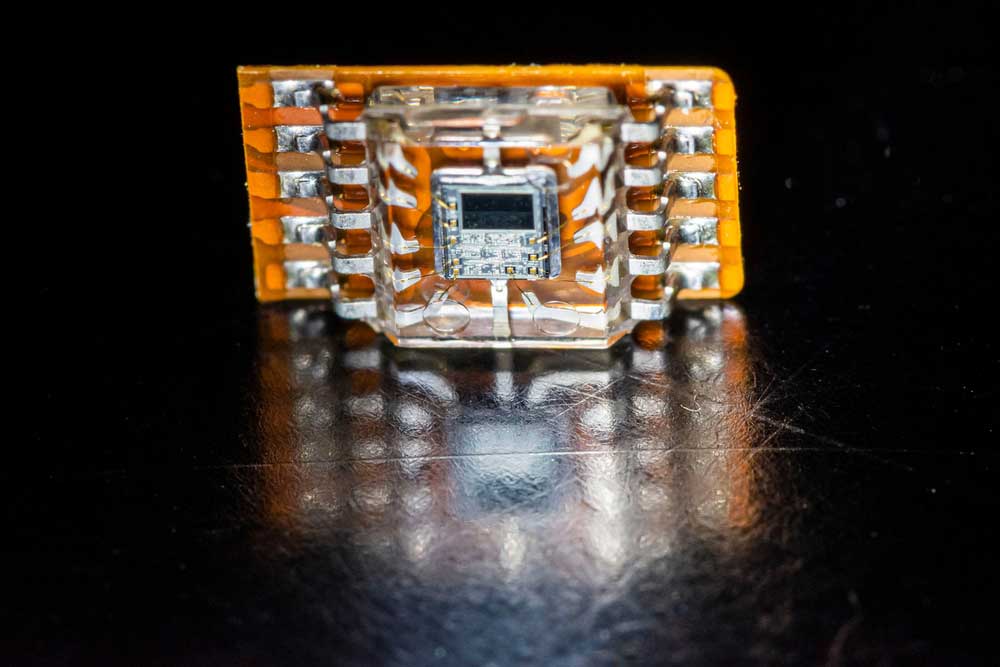
We will build this device using the MAX30100 pulse oximeter sensor.
But first, let’s look at the properties of blood when oxygenated and deoxygenated.
Table of Contents
- Oxygenated/Deoxygenated Blood Properties
- How The MAX30100 Sensor Works
- MAX30100 Sensor Features
- Arduino Pulse Oximeter Project
- Arduino Pulse Oximeter Project With an LCD Display Module
- Wrap Up
Oxygenated/Deoxygenated Blood Properties
When you breathe in, the blood protein hemoglobin in red blood cells carries this oxygen around the body.
The protein also transports carbon dioxide from the tissues back to the lungs for you to exhale.
So you always have oxygenated and deoxygenated blood circulating in your body, each with unique properties.

A hemoglobin molecule in red blood cells
Oxygenated blood absorbs more infrared light than deoxygenated blood but allows more red light to pass through.
On the other hand, deoxygenated blood absorbs more red light while allowing more IR to pass through.
Why is that? Hemoglobin gives blood its color.
When carrying more oxygen, it makes the blood turn bright red.
This color absorbs more IR and lets red light pass through.
But when transporting CO2, hemoglobin turns to a darker shade of red.
This blood color absorbs red light but allows more IR to pass through.
So the MAX30100 sensor has three primary components to function as an effective pulse oximeter.
- A red LED
- An IR LED
- A photodetector
How The MAX30100 Sensor Works
This sensor module shines one LED at a time, then detects the reflection.
The amount of light reaching the detector determines the heart rate and blood oxygen level.
A photo sensor/detector
So it features a heart rate & pulse oximeter sensor integrated circuit (MAX30100 chip) with low-noise analog signal processing.
We’ve already looked at how the device measures oxygen levels.
To recap, it checks the detected/reflected IR or red light signals on the photodetector.
The higher the red light detection levels, the higher the oxygen levels.
And the higher the IR detection levels, the lower the oxygen levels.
But how does it measure the heart rate?
Remember, oxygenated hemoglobin absorbs more IR light as it travels inside the arteries.
But as the heart pumps the blood, it creates bursts where blood pushes out at high and low-pressure intervals.
These intervals create pulses in the arteries with high and low concentrations of oxygenated hemoglobin.
So the amount of absorbed/reflected IR light will match these pulses.
Therefore, shining the IR light continuously on your finger creates a graph where the reflected IR light dips and rises.
This graph matches the pulse rate in your arteries, which is your heart rate.
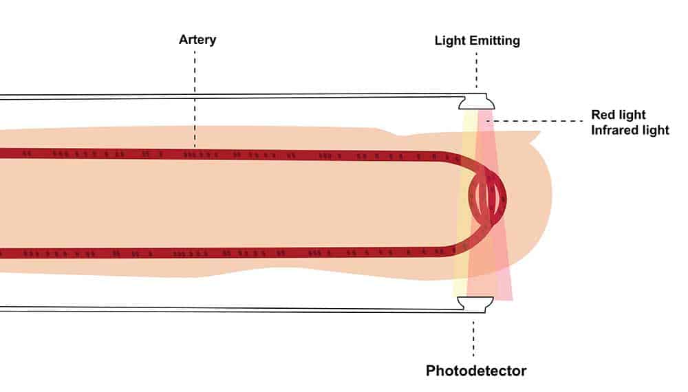
The reading principle of a pulse oximeter
So the module doesn’t use the red LED for heart rate measurement.
MAX30100 Sensor Features
The MAX30100 module has the following hardware features.
Power Requirements
This chip runs on 1.8V, while the LEDs require 3.3V.
So the module has 1.8V and 3.3V voltage regulators for powering using 5V or 3.3V.
Another vital feature to note is the module’s low power consumption.
It draws less than 600μA during regular operation and 0.7μA when on standby.
Such power consumption figures make the unit ideal for battery powering on wearables, smart watches, handsets, etc.
On-Chip Temperature Sensor
Ambient temperature changes can alter the module’s measurements.
So it has an on-chip temperature sensor to help calibrate the measurements to compensate for these changes.
This chip has an accuracy of +/-1°C and a die-temperature range of -40°C to 85°C.
FIFO Buffer
This module has an embedded FIFO buffer for storing 16 data samples.
So it can relieve the Arduino board from reading the data in real-time to reduce power consumption.
Interrupts
Interrupts allow the microcontroller to run other tasks as the MAX30100 collects and stores the data in the buffer.
You can enable these interrupts for these five sources:
- Power Ready: After a brownout, power-ready triggers on power up
- Heart Rate Data Ready: Triggers after collecting all heart rate samples
- SpO2 Data Ready: Triggers after collecting all SpO2 samples
- FIFO Almost Full: Triggers when the buffer is full and can’t store future data
- Temperature Ready: Triggers after completing the internal die temperature conversion
These interrupts affect the state of the INT pin, triggering it to a logic-low mode.
After clearing the interrupt, the internal resistor pulls it high because the pin is an open drain.
I2C Interface
This module has an I2C interface with two wires to connect to the Arduino board (SCL and SDA).
Also, it features a fixed I2C address: 0xAFHEX for reading and 0xAEHEX for writing.
Other features/technical specifications include the following.
- Peak red light wavelength: 650 – 670 nm
- Peak IR light wavelength: 870 – 900 nm
Arduino Pulse Oximeter Project
You’ll only need an Arduino UNO, the MAX30100 sensor, and jumper wires.
Hardware Connections
| Arduino UNO | MAX30100 |
| 5V | Vin/Vcc |
| GND | GND |
| A4 | SDA |
| A5 | SCL |
Circuit Diagram

You can connect the Vin pin to Arduino’s 3.3V or 5V pin, but we’ve chosen 5V.
Connect the Arduino board to your PC via a USB cable, launch the Arduino IDE, and paste the code below.
Code
Ensure you download the MAX30100 library before writing the code.


Code Explanation
After including the libraries, the code defines the update frequency of the reporting period between the samples to one second.
Next, we declare the pulse oximeter object (pox) and the variable for holding the time the last beat occurred.
The “onBeatDetected” function will display the word “Beat!” when a heartbeat gets detected.
Void Setup ()
We begin by setting the serial communication at 115200 bits every second in the setup function.
After that, the program prints the initialization message on the screen.
Next, we initialize the sensor. If it fails due to errors like:
- Improper I2C wiring
- Lack of power
- Wrong target ship
You will get the “Failed” message on the screen.
But if there are no errors, you will get the “Success” message.
The following line sets the current the sensor should use to power the IR LED (7.6mA).
Its default current draw is 50mA.
We reduce it because the high current draw can cause initialization issues.
Lastly, register the “onBeatDetected” callback function defined earlier.
Void Loop ()
This function begins by reading the sensor value using pox.update().
The if statement ensures the serial monitor prints the heart rate and oxygen level % each second.
After that, it sets the tsLastReport variable as the current time.
So when the loop runs again, it will run the if statement after one second, displaying the sensor readings.
Arduino Pulse Oximeter Project With an LCD Display Module
We can make a few adjustments by adding a 16×2 LCD using the same I2C communication as the pulse oximeter.
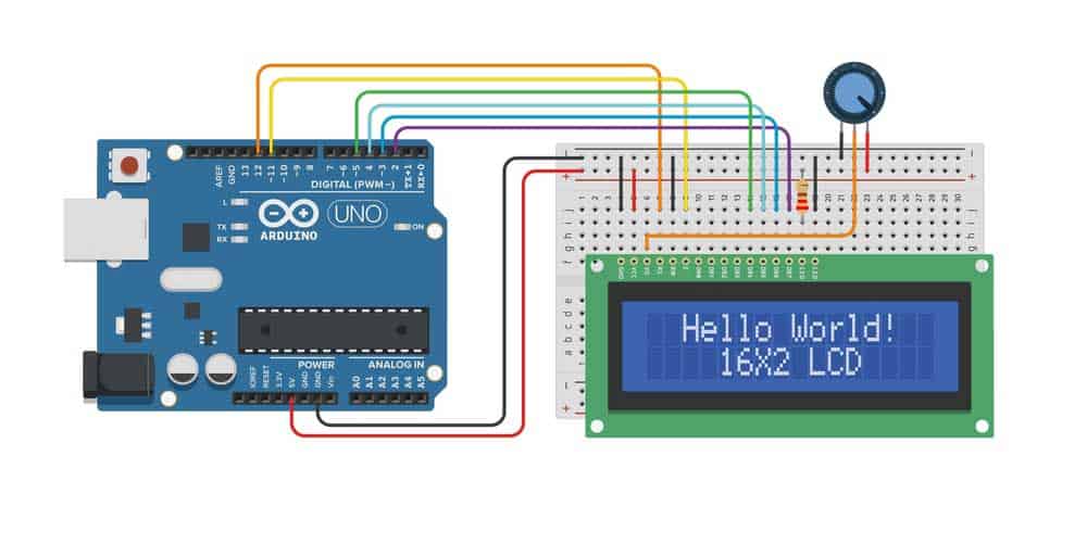
An Arduino UNO board connected to a 16×2 LCD
Hardware Connections
| Arduino UNO | 16×2 LCD |
| 5V | Vcc |
| GND | GND |
| A4 | SDA |
| A5 | SCL |
Circuit Diagram

Code
We’ll make a few modifications to the code to accommodate the LCD module.
But first, download this liquid crystal library and import it into the Arduino IDE.

Code Explanation
We don’t have to include the “Wire.h” library because it is already part of the liquid crystal library.
But we’ll create the LCD object with the address 0x27, 16 columns, and two rows.
In the setup function, the code initializes the LCD object, turns on the backlight, then prints the message “Initializing.”
After that, it waits for three seconds and clears the screen.
The LCD code goes in the if statement like the rest in the void loop function.
First, we use the LCD object to clear the display, set the cursor to the upper row, and print the heart rate.
After that, we adjust the cursor to the second row and print the oxygen level percentage.
The rest of the code is similar to the one written earlier.
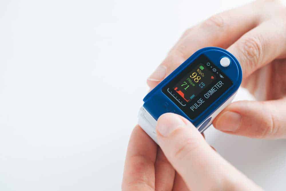
A pulse oximeter (note the oxygen saturation and pulse rate readings)
Wrap Up
There you have it!
An Arduino pulse oximeter you can port into a final product and sell to the market.
The beauty of this project is that the MAX30100 does all the heavy lifting.
So you only have to interface it with your microcontroller and write the code above to get the device running.
That’s it for today. We hope the article was insightful.
If you encounter any challenges implementing the project, contact us, and we’ll be in touch to help.