In this article, we will look at how to advance from the Arduino prototype to the final product after proving your project works.
Arduino boards are ideal for rapid prototyping, but you can’t use them to build the final manufacturable product because they are huge.
Picture fitting an Arduino Nano or UNO in a smartwatch. Impossible, right?
So after fine-tuning the project and ensuring it works, you have to move to the next step of making the final production product.
Here s a breakdown of the steps you need to follow.
Table of Contents
- Design the Microcontroller Circuit Schematic Diagram
- Design the Shield Circuit Schematic Diagram
- Design the PCB
- Order the Initial PCB Prototypes
- Develop the Software and Firmware for the PCB Prototype
- Test and Debug your Prototype
- Wrap Up
Design the Microcontroller Circuit Schematic Diagram
Since you used an Arduino microcontroller, the first step in transitioning to a final consumer product is to design a custom microcontroller circuit to replace the one used in the board.
And the easiest way to go about this process is to pick the same microcontroller as the one used in the Arduino model you used in your project.
All Arduino models (except for the 101) run on Atmel microcontrollers, and most of them have Atmel AVR 8-bit microcontrollers, such as the Atmel ATmega328p.
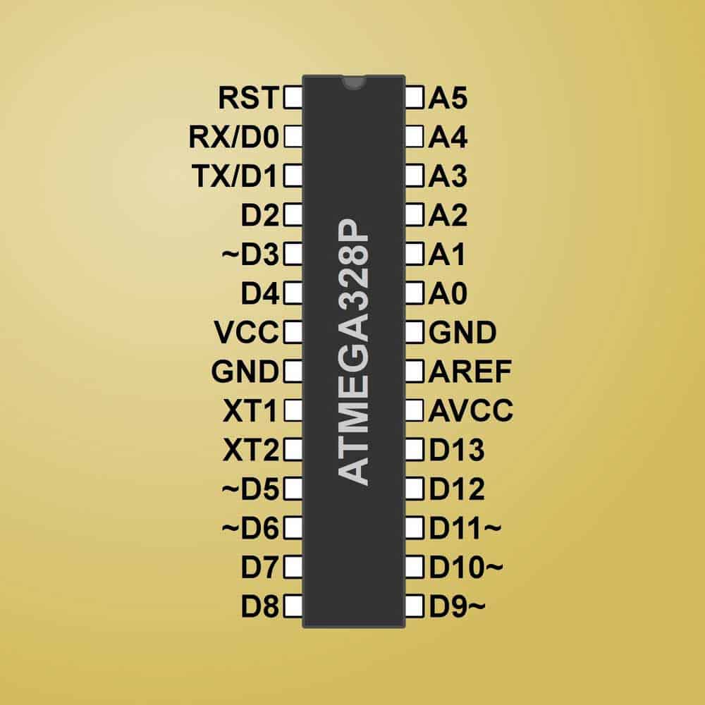
A pinout diagram of the ATmega328p
Found in the UNO, this chip is a thru-hole dual-inline package (DIP) version that plugs into a socket.
The socket allows easy replacement if the microcontroller gets damaged in the development kit.
But a socketed chip is not a good idea for the final product because it will take up too much space.
A surface-mount package is tinier than the DIP, and the lack of a socket makes it even more compact.
And besides size, SMT packages are cheaper than thru-hole components, and their assembly costs are lower.
So the production process will cost less when mass-producing the finished products if they have SMT chips.
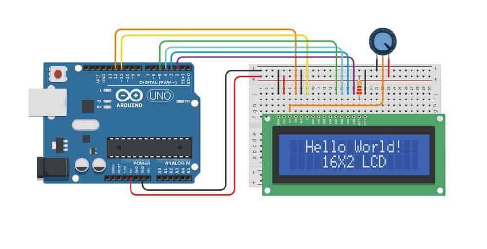
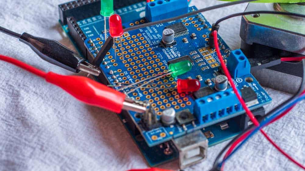
An Arduino LCD project (note the ATmega328p chip on the board)
Can You Use Other Microcontrollers?
Yes. And you can get a more powerful chip with more memory, such as an ARM 32-bit Cortex-M microcontroller, which is cheaper than the ATmega328p.
But since the chip is not the same one present in the Arduino board, you might have a more challenging time or work when transitioning from the Arduino prototype to mass production.
However, if you know your way around electronic products and coding, you can use the more advanced chips.
Arduino Prototype to Final Product: Board Schematic
Whether you use the Arduino Leonardo, UNO, Mega, etc., you must analyze the board schematic to determine which other components you need.
The good thing is that Arduino has an open-source architecture, meaning you can get these PCB layouts for free. Let’s look at the Arduino UNO PCB design.
On the board’s schematic diagram, you will notice it has two integrated chips: U3 and ZU4. U3 is an ATmega16U2 chip, while the ZU4 is the ATmega328p.
Since the ATmega328p does not feature a USB programming port, the ATmega16U2 handles USB to UART conversion.
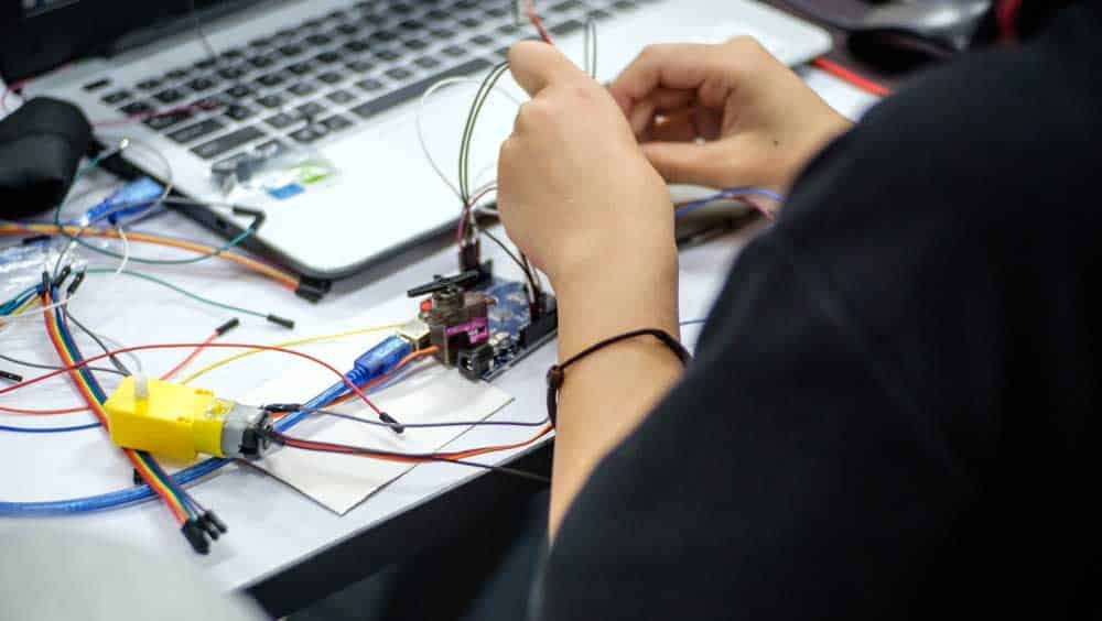
An Arduino UNO board connected to a computer via its USB port
So if you want to build a commercial product that requires USB communication via a USB port, you’ll have to include the U3 in your PCB prototype.
But the best option is to use a microcontroller with a built-in USB port, such as the ATmega32U4 found in the Arduino Leonardo. However, the chip is pricier.
Arduino Prototype to Final Product: Power Circuitry
Another critical factor to consider is the support circuitry around the primary microcontrollers.
While still considering the UNO, each of the two chips has a 16 MHz clock, several serial interfaces & GPIO pins, decoupling capacitors, etc.
But one of the critical areas to look at is the power supply circuit. The board features a dual operational amplifier (U5), one being a DC voltage comparator that determines if the board is getting its power from a USB port or 6-20V DC input.
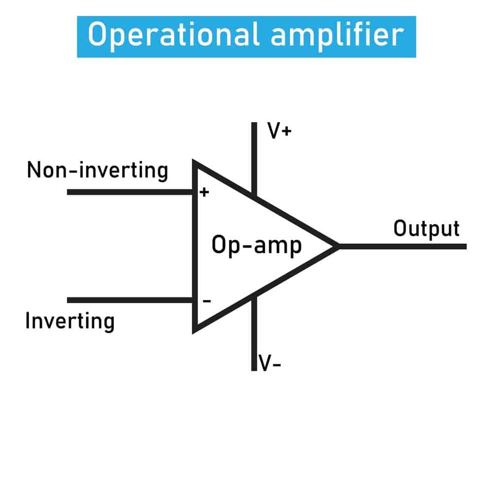
An op-amp circuit symbol
If it’s coming from the 6-20V DC input voltage, the onboard linear regulator converts it to a 5V power supply. Otherwise, the board switches to USB power.
Using a linear regulator is okay for some products but is inefficient for battery-powered products or those that consume high current levels.
So we don’t recommend using the NCP1117 if the input voltage from the power source is significantly higher than what you need to run the circuit.
Consider using a switching regulator instead, which is more efficient. But there is a catch. This regulator is more complex than the linear type.
So if the battery voltage that flows into the device is slightly higher than 5V, you can consider using a linear regulator.
Arduino also creates 3.3V, and we can use a linear regulator for this process because the differential voltage from the 5V already produced by the switching regulator (buck converter) is minimal (5V-3.3V=1.7V).
So the energy losses are minimal.
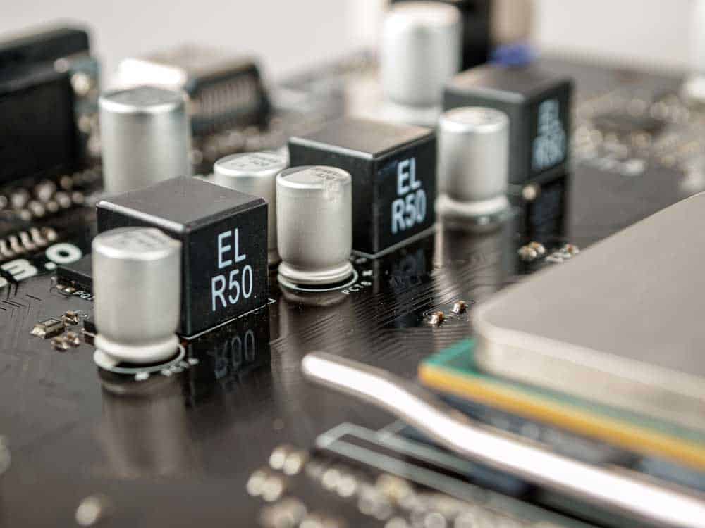
Voltage regulator modules in a PCB
The UNO uses the LP2985 LDO regulator from Texas Instruments for this task, and you can use the same for the PCB prototype.
Design the Shield Circuit Schematic Diagram
Once done with the Arduino board, check the design schematics for any shields you have used for your project.
While you can custom design some shields, such as for sensor and motor control, we don’t recommend doing the same for wireless connectivity shields due to their complexity.
These include Wi-Fi, Bluetooth, GSM, and GPS shields.
An Arduino board with a shield stacked above it
Buying a surface-mounted module and soldering it directly to the board is a safer alternative.
So consider leaving provisions (pins) for connecting the component to the circuit.
Another benefit of soldering external pre-certified modules is it simplifies the process of certifying your finished consumer product.
Design the PCB
After laying out the microcontroller, power, and shield schematics, the next step is to integrate the design into a compact printed circuit board for the final product.
Designing microcontroller circuits running at 16 MHz is simple, but things become more complex once you integrate wireless functions and fast clock speeds that hit hundreds or thousands of megahertz.
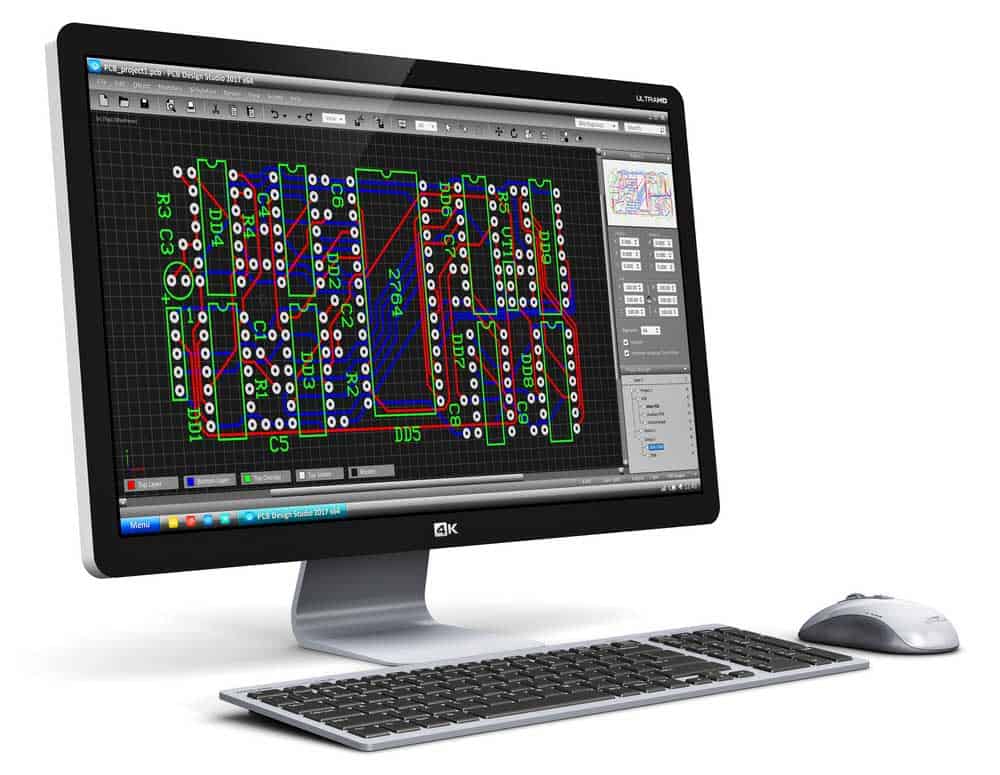
PCB designing using CAD software
For instance, you must correctly lay out the wireless antennas for proper matching to ensure maximum power transfer.
And you’ll most likely need a pi-matching network for tuning the antenna to achieve maximum efficiency.
Two other things you have to consider are the following.
- Clock (plus their load capacitors) placement
- Decoupling capacitor placement
The clock should be near the microcontroller pins, while the decoupling capacitors should be close to the pin requiring decoupling.
Order the Initial PCB Prototypes
Once you complete the PCB design, contact your PCB manufacturer to get the initial prototypes made.
You can ask your manufacturer to help you review the design using their in-house team of engineers or look for another expert to give an independent schematic and PCB design review before fabrication.
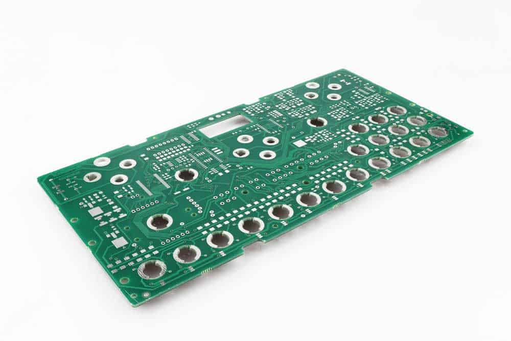
An unassembled PCB prototype
Getting an independent design review is to help detect and rectify as many errors as possible before production because they can be expensive later.
Although you can spot these faults when testing the PCB prototypes, the earlier you detect them, the better.
Once everything looks good, order 5-10 prototypes for testing and debugging.
Develop the Software and Firmware for the PCB Prototype
This step involves porting your Arduino code into the native firmware code for the microcontroller.
The process is easier if you are dealing with a chip in the same family as the one in your Arduino board.
It is vital to note that Arduino embeds an In-System Programmer (ISP) or In-Circuit System Programmer (ICSP) into their boards to allow USB-port programming via a USB-to-UART converter.
But you’ll have to use a serial port like SPI, UART, JTAG, or SWD to program the custom microcontroller circuit.
And you’ll need the ISP hardware to connect to the microcontroller.
Also known as a debugger, this programming device lets you view the microcontroller’s inner workings after porting the code to debug any errors.
Remember that software development on the Arduino IDE gives you several library functions to simplify coding.
So you must port the library codes for these functions to the microcontroller code to make the software work.
Test and Debug your Prototype
It is rare to have the first electronic prototype working seamlessly unless the product design is simple.
So test and debug the prototype PCB circuits while improving the circuit design.
If you feel the changes have fixed the issues, order the second batch of 5-10 PCB prototypes using the improved circuit designs and repeat the process until you get everything right.
Wrap Up
In conclusion, migrating your project from the Arduino prototype to the final product consists of a few steps, with the three initial stages being the most critical.
Once you get a functional prototype, porting the code is relatively easy, especially if you use a microcontroller in the same family as the one on your Arduino board.
That’s it for this article. Comment below to let us know your thoughts and sentiments about the piece.