We will look at two ways of implementing Arduino servo motor projects below.
Robots can interact with their environment by manipulating and moving objects.
Such interactions require actuators to provide precise movements, and you can use hydraulic/pneumatic systems, shape memory alloys, or servo motors as actuators.
But servo motors are more popular, especially for small robots, because they are easy to implement.
Let’s look at how to build these projects, beginning with defining a servo motor.
Table of Contents
What Is a Servo Motor?
A servo motor is an AC/DC motor type that uses an encoder (position & speed sensing device and control unit) to provide precise angular/linear control of the output shaft.
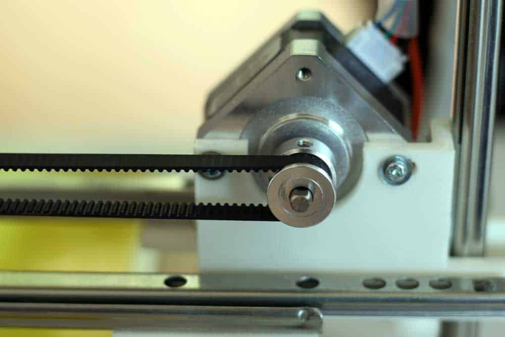
A servo motor with a belt attachment
The device uses the PWM (Pulse Width Modulation) technique to control the shaft’s rotation speed, and such precise movements make the motors ideal for the following applications.
- Steering a robot’s front wheels
- CNC machines
- Pivoting sensors on robots
- Horizontal and vertical control of security cameras
- Solar tracking systems to maximize sunlight harvesting
How Servo Motors Work
Servo motors are easy to wire in your project because they come as complete units with the motor driver built-in.
The devices contain the following four primary components:
- DC (or AC) motor
- Gear train
- Potentiometer
- Control unit
Also, they usually come with servo horns to connect to the output shaft.
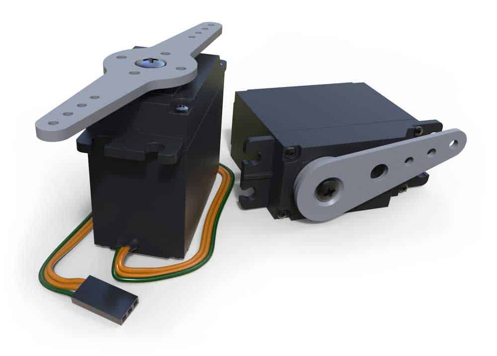
Two servo motors with horns attached
The control unit acts as the brains behind the system, while the potentiometer gives position feedback to adjust the motor to rotate to the target position.
It sends the instruction to the control unit’s error amplifier, which powers the motor to spin to the required angle.
This servomechanism technique (shortened to servo) gives the motor its name.
It creates a closed-loop system that takes in negative feedback from the potentiometer to calibrate the motor’s direction and speed for maximum accuracy.
The gear train increases the motor’s torque output to handle heavier tasks.
How To Control Servo Motors Externally
You can control a servo motor’s position externally by sending several electrical pulse inputs at different lengths.
Servo motors expect pulses every 20ms at 50Hz, with each pulse’s length determining the output shaft’s position.
For instance, if the motor receives one short 1ms pulse in the 20ms duration, it stays put at zero degrees (won’t spin).
But if it gets a 1.5ms pulse/20ms duration, it will turn 90°. A longer 2ms pulse will turn the motor 180°.
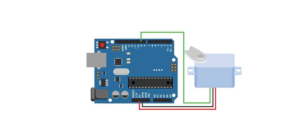
How to interface an Arduino board with a servo motor
So with such a motor, supplying it with a varying pulse length from 1ms to 2ms and back to 1ms will turn it from 0° to 180° and back.
The purpose of the servo horn is to show you this rotation during testing or development.
But it is vital to note that the pulse duration to rotation ratio can vary depending on the servo motor manufacturer.
Also, there is no standardized relationship between the pulses and motor position.
So you should adjust the Arduino code to determine the motor’s range.
Arduino Servo Motor Projects
Since you now understand how a servo motor operates, we will implement two projects to show you how to run the device.
The first will have no external input, meaning the motor will rotate independently.
But we’ll use a potentiometer on the second project to provide an external signal that controls the output shaft’s position.
You will need the following components for these projects.
- An Arduino UNO board
- Servo motor (such as the SG90)

A vector image of the SG90 servo motor
- 10KΩ potentiometer
- 5V battery/power adapter (DC power supply)
- Breadboard
- Jumper wires
- USB cable
And before we get into the projects, you should know that servo motors usually have three pins or wires.
- Red V-in 5V power supply wire
- Brown wire (GND) (can be black in some servo motor brands)
- Yellow/orange control signal wire
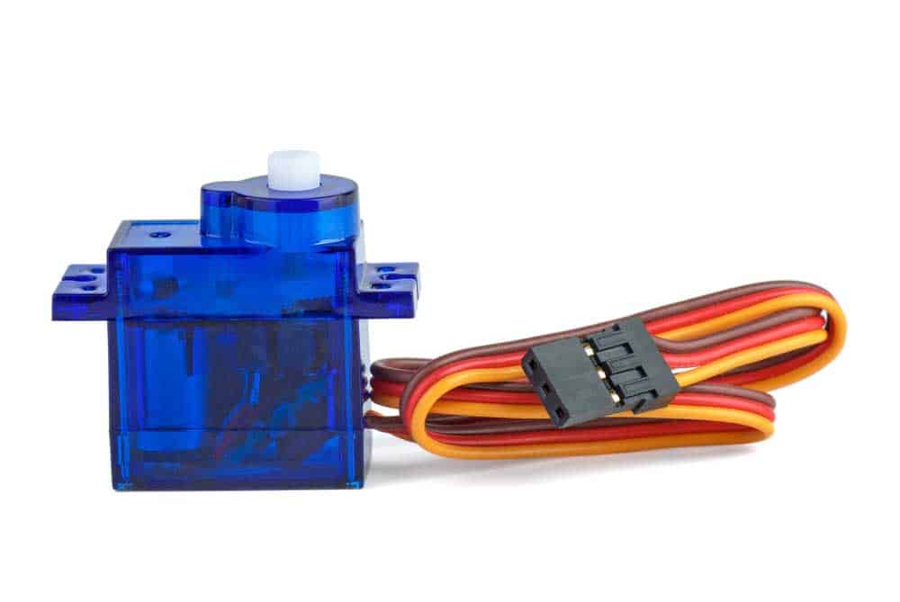
A tiny servo motor with three pins/wires (red, brown, and yellow)
Project 1 (Sweep)
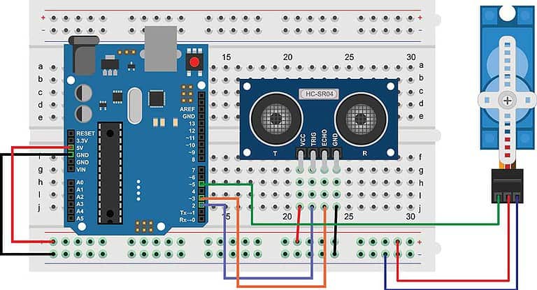
We’ll use the Arduino IDE’s servo motor sweep code for this example. Connect the components as shown below.
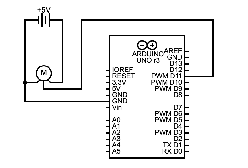
Arduino sweep circuit diagram
The Arduino board is the primary processing module in this circuit because it provides the PWM signals and has an ADC (Analog-to-Digital Converter) to help map the user input.
Please note that you don’t need the potentiometer for this project because there’s no need for manual motor control.
We recommend powering the Arduino board using its USB port, but you can use the Vin pin if you have an unregulated power source.
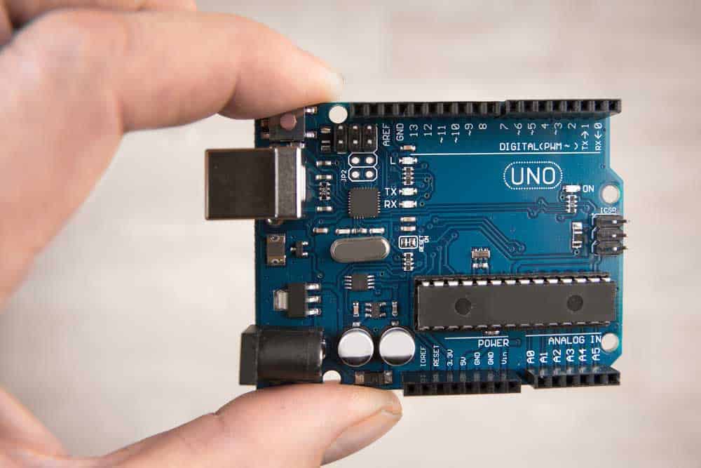
An Arduino UNO board (note the USB port, digital PWM pins, and analog pins
Code
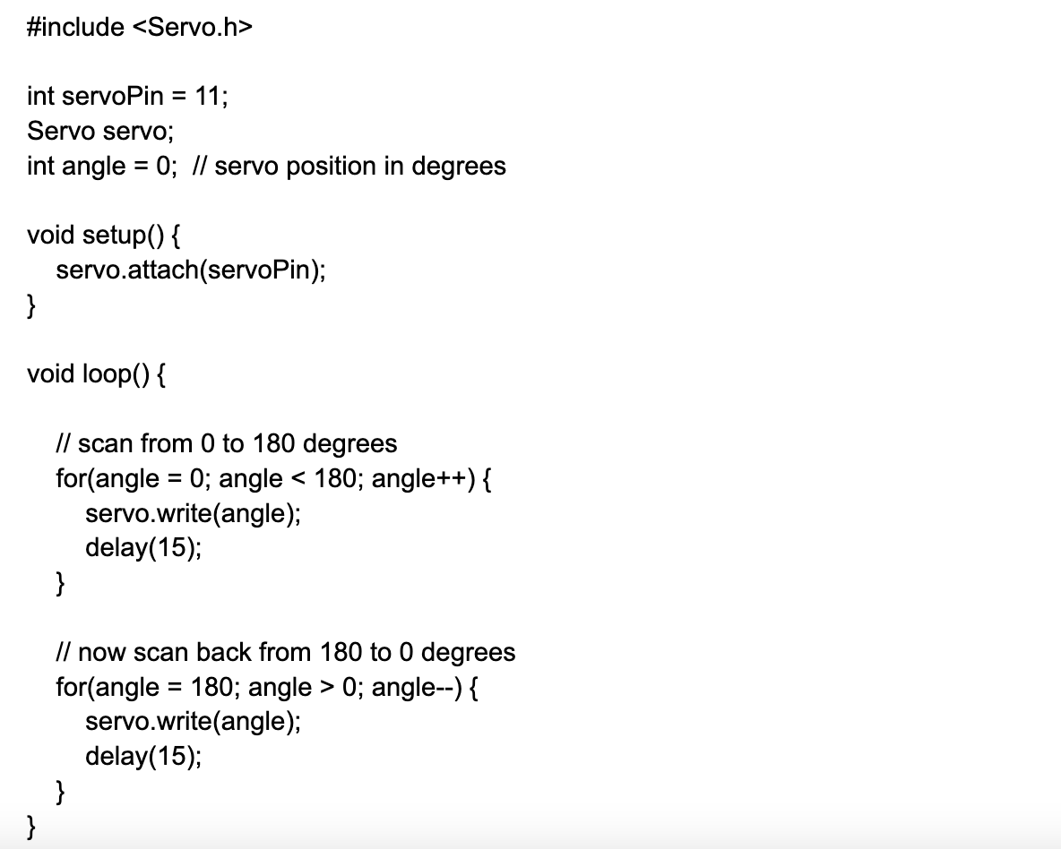
Arduino has a servo library that makes it easier to build basic servo motor projects.
So open the Arduino IDE, then go to File>Examples>Servo>Sweep. You should get this code.
Code Explanation
After including the library, you must set the pin the servo motor’s control pin uses to connect to the Arduino board.
In our case, it is pin 11, and you’ll attach it inside the void setup function.
Next, create the servo project, and you can define a maximum of eight to control eight servo motors.
After that, declare the angle variable to store the motor’s current position.
The core of the code is in the void loop function, which has two FOR loops for rotating the servo from 0-180° and back while incrementing/decrementing the servo’s position (angle variable), respectively.
This movement causes the motor horn to spin halfway around and back, which can be ideal for turning car wipers.
But you might encounter issues with the circuit created earlier because motors usually consume more power when starting up.
So if you operate the servo directly from the Arduino board without a servo driver, you can cause the board to reset, which will stop the motor.
So consider positioning a high-capacity electrolytic decoupling capacitor across the +ve and -ve input power lines.
A 450µF – 1000µF capacitor should be sufficient.
Its longer lead should connect to the 5V +ve line, while the short pin connects to the -ve line.
This component should provide a current boost to start the motor effortlessly.

A 10µF (25V) electrolytic decoupling radial capacitor mounted on a breadboard
Project 2 (Knob)
As the name suggests, this project uses a knob (potentiometer) to adjust the servo position manually.
This project gives you more control over the movements, which is what you’d need for robotics, camera movements, etc.
Connect the components as shown below.
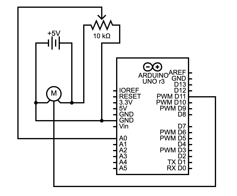
Arduino knob circuit diagram
Like in the Sweep project, we recommend powering the Arduino board using its USB port, but you can use the Vin pin if you have an unregulated power source.
Code
Go to File>Examples>Servo>Knob on the Arduino IDE, then upload the code to your board.
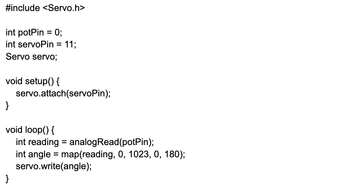
Code Explanation
This code is more straightforward and shorter than the sweep code.
It introduces a new variable (potPin) that sets the Arduino pin connected to the potentiometer’s output (analog pin A0).
The code continuously reads the analog voltage from this pin in the void loop function.
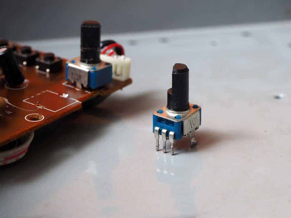
A 10K potentiometer
Since the Arduino UNO board features a 10-bit ADC, the analogRead function returns a value between 0 and 1023.
So we have to map these values to an angle between 0° and 180°, then pass this variable to adjust the motor position.
Possible Project Improvements/Expansions
You can try replacing the potentiometer with a joystick to make the servo motor control more realistic in your robotics or camera movement projects.
And with the sweep code, you can include two motors and two servo objects to turn double wipers.
Wrap Up
Building any Arduino servo motor project is relatively straightforward, but you must begin by setting up the motor control code.
Once this part works, you can introduce improvements to suit your project.
That’s it for this article. Reach out if you need further guidance, and we’ll be in touch to help.