Tanks are large, armored vehicles used by the military, but you can build a tiny Arduino tank version as a toy gift or school project.
Building this tank is similar to making a robot, but you should equip the vehicle with chain wheels instead of two wheels to resemble the military tank.
Also, it should have a functional gun that rotates at the top and fires plastic balls, plus a radio controller to give you remote control.
So if you’re familiar with Arduino robots, this project should be a walk in the park. Let’s look at how to build this tank using an Arduino board.
Table of Contents
What You Need
The project requires the following components.
- Arduino Nano board (R3)
- L298N motor driver
- Two DC motors
- L7805CV servo motor driver
- Two servo motors
- Darlington ULN2803 assembly
- APC220 or NS-12 radio module
- INA219 battery monitoring module
- Two jumpers
- Tank chassis, lid, and gun
- Battery
- Several capacitors (shown in the circuit diagrams below)
Tank Hardware Connections
The Arduino Nano board is the brains of the tank, and we’ll connect it to almost all components.
But since the project will consume lots of power, we’ll have to use a customized power bank with four batteries and five outputs to power the system.
Power Bank Outputs
These power bank outputs consist of the following pins.
| Pin Number | Function |
| 1 | Negative pin |
| 2 | On/Off |
| 3 | GND |
| 4 | Positive (1.25-16V) |
| 5 | Positive control pin (10-16.8V) |
You can build any custom power bank with more or fewer batteries, but it should have these five pins for this project.
Radio Module Connection
Next, we’ll hook up the communication module to enable the remote control function on the tank. Here’s how to do it.
| Power Bank | Arduino Nano |
| 1 | N/A |
| 2 | N/A |
| 3 | GND |
| 4 | Vin |
| 5 | N/A |
The power supply’s pins one and two should connect to the tank’s body switch.
| Arduino Nano | APC220 Module |
| D1/Tx | RxD |
| D0/Rx | TxD |
| GND | GND |
| 5V | Vcc |
Also, connect the power bank’s GND pin to the radio control module’s ground pin. Here’s what you should have after making the connections above.
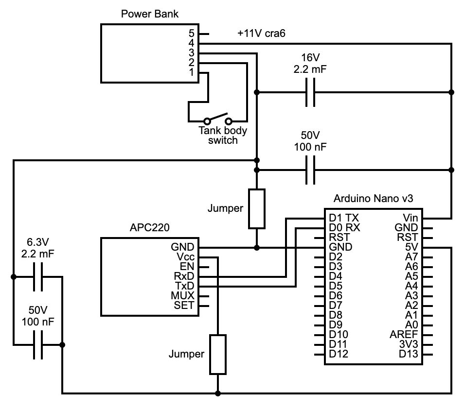
The radio-module connection circuit diagram
DC Motor Connections
After that, we’ll hook the DC motors to the Arduino board using the L298N motor driver.
All components use the power bank’s +11V cra6 connection (pin4) as their power supply (except the battery monitoring module).
| Arduino Nano | L298N |
| Vin (connects to the battery’s +11V) | +12V |
| GND (connects to the battery’s GND) | GND |
| D3 | ENA |
| A3 | IN1 |
| A2 | IN2 |
| A1 | IN3 |
| A0 | IN4 |
| D5 | ENB |
| L298N | Motors |
| Right motor | OUT1 & OUT2 |
| Left motor | OUT3 & OUT4 |
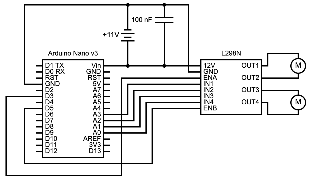
DC motor connections circuit diagram
Servo Motor Connections
The tank’s gun sits on the rotating tower, which has a swivel bracket to turn the firing chamber left/right and raise/lower it.
These operations require two servo motors, which we’ll power using the L7805CV motor driver, as shown below.
| Arduino Nano | L7805CV |
| Vin (connects to the battery’s +11V) | IN |
| GND (connects to the battery’s GND) | GND |
| Arduino Nano | Servo Motors |
| D10 | Servo incline signal pin |
| D9 | Servo turn signal pin |
| GND | GND pins on both motors |
| L7805CV | Servo Motors |
| OUT | Power pins on both motors |

Lights Assembly
The tank has three LED lights: two headlights and one on the gun. We’ll need the Darlington ULN2803 assembly to power these components.
| Arduino Nano | ULN2803 |
| GND (connects to the battery’s GND) | Pin 9 |
| D12 | Pins 1 & 2 |
| D11 | Pins 3 & 4 |
| D4 | Pins 5 & 6 |
| D2 | Pins 7 & 8 |
Each headlight will have a separate resistor (470Ω), and the two will jointly connect to the ULN2803’s pins 11 and 12.
On the other hand, the gun’s light will connect to the ULN2803’s pins 15 & 16. But all three will draw power from the battery directly.

Light assembly circuit diagram
Battery Monitoring Module
Lastly, we will set up the battery monitoring system using the INA219 module, the only component that connects to the power bank’s 10-16.8V +ve control pin.
| INA219 | Power Bank |
| Vin | Pin 5 (Positive control pin (10-16.8V)) |
| GND | GND |
The Arduino board will draw power from the power bank’s pin 4 (as usual), then connect to the battery monitoring module, as shown below.
| Arduino Nano | INA219 |
| 5V | Vcc |
| GND | GND |
| A5 | SCL |
| A4 | SDA |
Follow this circuit diagram to link the components.

Assemble these components inside the tank chassis, then set up the remote controller.
Universal Remote Controller Assembly
You’ll need the following primary components.
- 7-9V power supply
- INA219 battery monitoring module
- Push button switch
- APC220
- HC-12
- HC-05
- Two ULN2803 modules
- Arduino Mega
Circuit Diagram

Code
Download these two code files for the Arduino transmitter (universal remote controller) and receiver (tank), then paste them to your IDE and upload each to the respective board.
After that, run the tank and try to fire the plastic balls.
Wrap Up
As you can see, this project is slightly more complex than the Arduino project we had looked at earlier, but it is worth the effort.
However, if you encounter challenges with the implementation or getting the parts (such as the tank chassis), contact us, and we’ll find a way to get them to you.