Whenever you hear of nrf24l01 Arduino projects, think of a setup that allows wireless communication between two microcontrollers.
In our article today, we intend to cover the operation of the nrf24l01 module and provide examples of different ways to interface with Arduino.
It is a worthwhile project to try out, and we hope you’ll clearly understand its working principle at the end of this guide.
Further, as we’ll highlight, you should be able to set up the module in three different formations.
Table of Contents
- Why Interface nRF24L01 with Arduino?
- Characteristics of the nRF24L01 Transceiver Module
- How the nRF24L01 Module Works
- nRF24L01 Module Variations
- Example 1: Interfacing nRF24L01 with Arduino
- Example 2: Bi-directional wireless communication between two Arduino boards.
- Example 3 – Sending multiple variables in a single package
- Applications of NRF24L01 Modules
Why Interface nRF24L01 with Arduino?
Our cardinal aim is to illustrate how to initiate wireless SPI communication between two Arduino boards.
The nRF24L01 module, in this case, is the component that facilitates this communication.
On the other hand, the Arduino is a simple microcontroller allowing you to input a range of functionalities into your project.
Therefore, depending on your desired outcomes, you can control it from your Arduino.
It all depends on the codes that you load onto the Arduino.
Interfacing the Arduino to the module is imperative in facilitating communication in projects where wires are impractical.
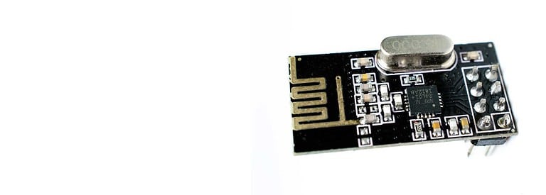
Characteristics of the nRF24L01 Transceiver Module
The receiver or transmitter module NRF24L01 with antenna
- It operates on the 2.4 GHz band and has baud rates between 250 kbps and 2 Mbps.
- The communication range of the module is extensive, especially at low baud rates and open spaces. It can communicate with a device at a distance of 100 meters.
- It features an adjustable radio frequency power output, and the module allows you to choose between channels in 1MHz portions.
The table below further gives the specifications of this module.
| Feature | nRF24L01 Module Specification |
| Frequency range | 2.4 to 2.5GHz ISM band |
| Maximum output power | 0 dBm |
| Data Rates | 250Kbps / 1Mbps / 2Mbps |
| Maximum operating current | 12.3mA |
| Logic inputs | 5V tolerant |
| Communication Range | Up to 100m in open space |
How the nRF24L01 Module Works
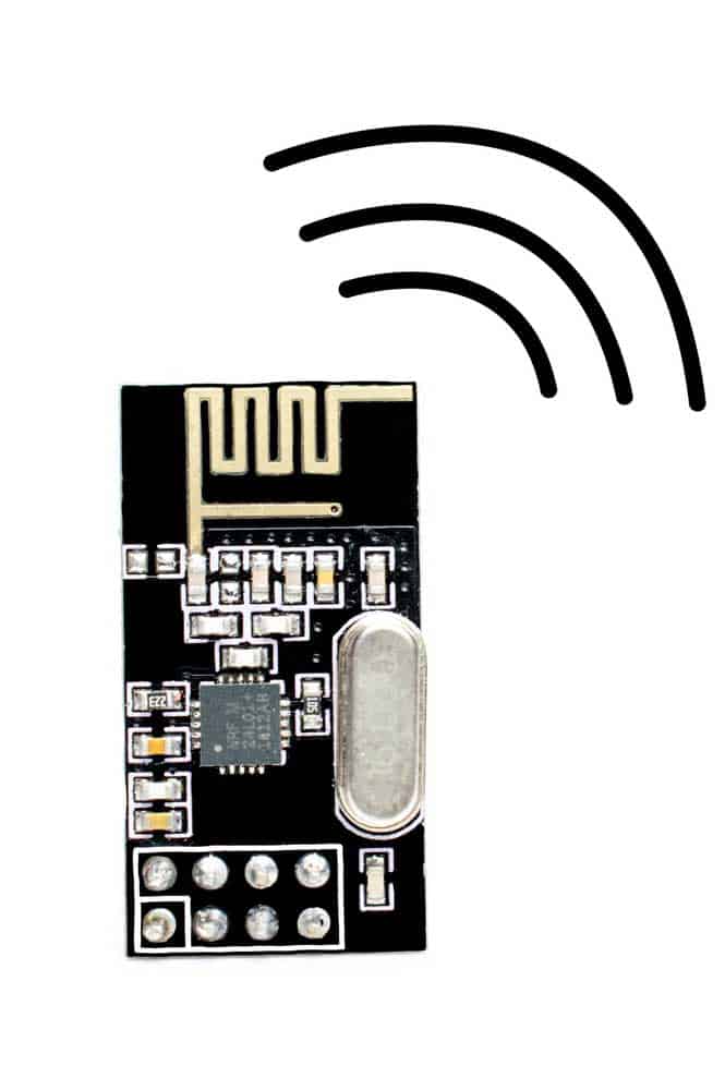
An NRF24L01 module.
It is primarily a communication module with 125 channels, each with several addresses.
Therefore, each respective channel can simultaneously link with six other modules.
This makes it one of the most effective communication modules. In addition, the modules are frugal in power consumption.
On average, each will use 12mA during significantly low communication.
Earlier, we indicated that the module has an operating voltage between 1.9V and 3.6V.
Nonetheless, it can connect with the 5V Arduino logic without needing a logic-level converter.
nRF24L01 Module Pinout
The three main SPI pins on the module include MOSI, MISO, and SCK. You need to connect these pins to the Arduino SPI ports during interfacing.
The other pins include the CE and CSN terminals you should link to your Arduino’s digital pins.
They are imperative in controlling the module, primarily changing its condition between the standby and active modes.
Finally, the module features an Interrupt pin which you don’t have to connect to anywhere during use.
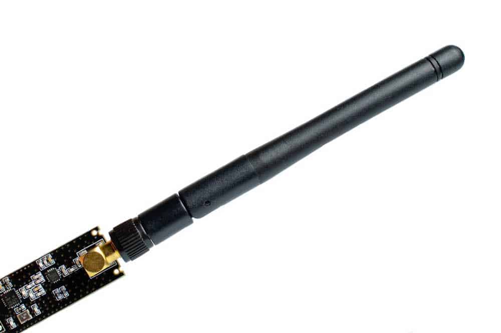
nRF24L01 Module Variations
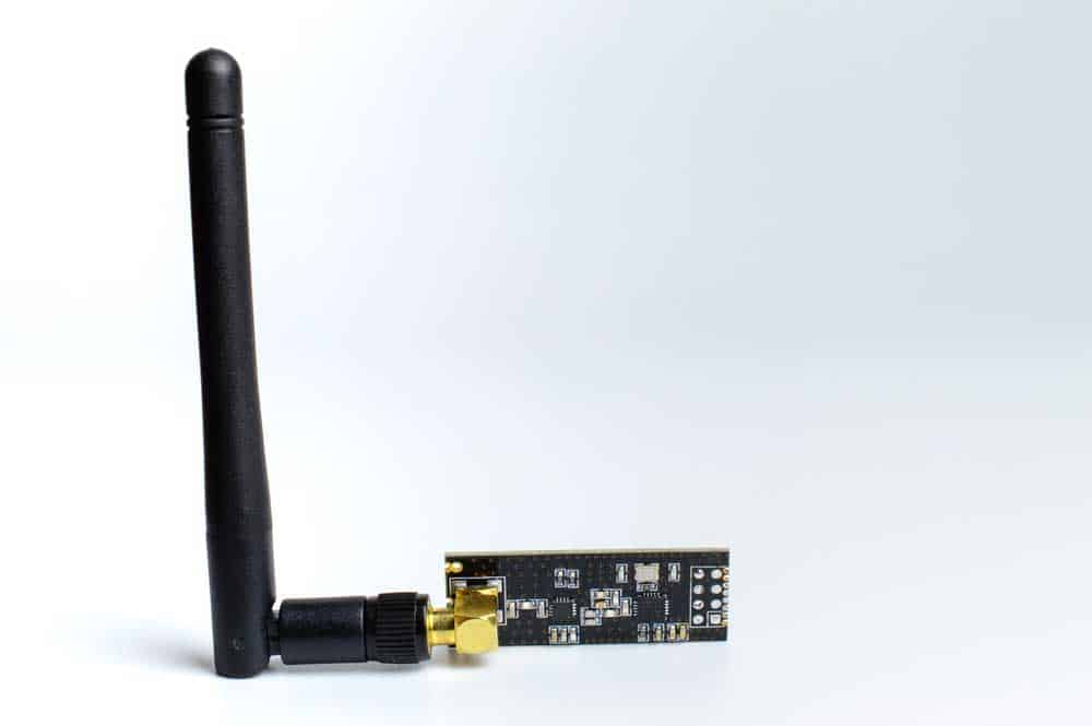
An nRF24L01 with a duck antenna.
Below are the three main types of the nRF24L01 module.
- Module with onboard antenna– It is small and compact but has a limited transmission range. The maximum range with the antenna for this module is 100 meters.
- Module with an SMA connector– This has an improved transmission range thanks to the connector feature, which enables you to plug a duck antenna into it.
- Lastly, we have a variation of the type above. This module features an FX2401C chip to complement the duck antenna.
The chip delivers additional features, such as a power amplifier and a Low-Noise Amplifier, to boost the signal.
Hence, the ultimate transmission range of this module is the highest of the three and can reach up to a kilometer.
Example 1: Interfacing nRF24L01 with Arduino
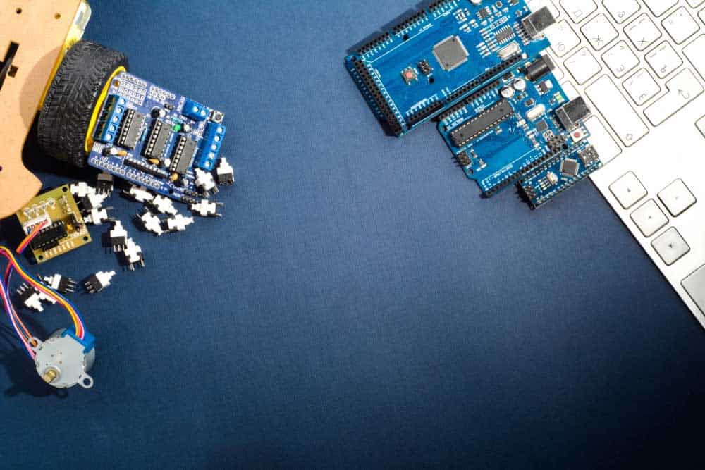
An Arduino board in a robotics project.
We’ll highlight the three main examples of how you can interface nRF24L01 with Arduino.
Components Required
- Two Arduino Uno boards, Arduino Nano or Arduino Mega
- Two NRF24L01 modules
- A hookup wire
- Breadboard
- Arduino IDE
Connection Setup
SPI Pins on Different Arduino Boards
On the parts of components above, we mentioned that you could use various types of boards.
But noteworthy, there are different types of SPI pins for every Arduino board.
| Arduino Board | SS | MOSI | MISO | SCK |
| Arduino UNO | 10 | 11 | 12 | 13 |
| Arduino Nano | 10 | 11 | 12 | 13 |
| Arduino Mega | 53 | 51 | 50 | 52 |
Loading the Code to the Arduino Boards
Once you have made the connection, you must load the code to the Arduino IDE.
Primary, you will need to load the RF24 library to your Arduino IDE as, in most cases, it is unavailable from the Arduino library.
Nonetheless, you may still find it on your IDE, so before loading it afresh, check out by entering the following prompt on your library: ‘rf24.’ If the code is present, install it.
Next, here are the primary codes you’ll need to upload on the respective IDEs:
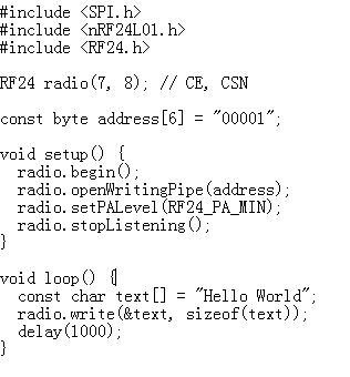
Arduino 1 (Transmitter Code)
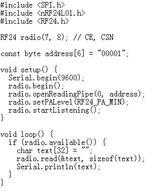
Arduino 2 (Receiver Code)
Code Description
First, you need to create an RF24 object for the RF24 library you created above by defining the SPI pins. In this case, the CSN and CE pins.
Now the other functionality we’ll include is a byte array or the address to facilitate the communication of our nRF24L01 modules.
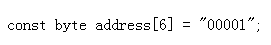
Our code also allows you to switch the receivers communicating with your transmitter.
All you need to do is tinker with the above 5-letter string in the code.
Nonetheless, in our case, we’re just interested in the included receiver. Hence we’ll use the same code for both modules.
Next, update this information on the receiver code and have the radio.setPALevel() function for the power amplification functionality.
You can set the amplification to a limited state as primarily your modules are very close together.
Check out the code:

Note: If you set up your power amplification at a ‘HIGH,’ you must include bypass capacitors in your circuit.
The ideal placement should be between your module’s 3.3V port and GND.
It will significantly improve the stability of your circuit’s voltage.
Our next part is to introduce a radio.stop Listening() function will aid in defining the respective roles of the two modules when we use it in tandem with the radio.startListening() fuction.
Hence, we’ll include the Start Listening Function at the receiver and the Stop Listening Function at the transmitter.
Next, on our code, we need to write our first message on the void loop part, as illustrated below.
Note that this code is on the transmitter end.

Similarly, we need to enable the receiver to read the message we have sent from the transmitter via the code below.

Finally, run the serial monitor, and you’ll receive the Hello message printout on your display.
Now we have created a code that makes communication between two Arduino boards.
Troubleshooting Common Circuit Issues
In this setup, there are two main issues we’re likely to encounter, and here, we’ll highlight their solutions.
Fixing power supply noise
Our project is an RF circuit meaning that its likely to have frequent power supply noise interruptions.
But you can solve this issue by including a 10uF capacitor on your circuit’s power supply line.
Fixing the Insufficient power problem
Another issue you’ll most likely encounter is that your NRF24L01 module may not receive sufficient power from the Arduino board power supply.
Hence, powering it with a battery or any other viable external power source would be best.
Example 2: Bi-directional wireless communication between two Arduino boards.
In this example, we’ll have a setup similar to the above, but in this case, we’ll introduce a bi-directional wireless communication functionality.
This means that unlike above, your receiver module can also wirelessly send a signal to the transmitter.
We’ll also introduce other components, including a joystick module, servo motor, push button, and an LED, as illustrated in the schematic below.

nRF24L01 Arduino Transmitter Code
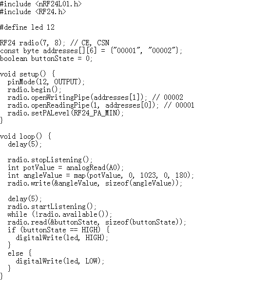
nRF24L01 Arduino Receiver Code

Code Explanation
Unlike in the first example above, in this case, we need to formulate different addresses to facilitate bidirectional communication.
Hence, here’s what our first part of the code will look like:
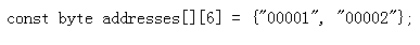
The rule of thumb when defining the addresses is that you must ensure your primary Arduino’s writing address is similar to your secondary Arduino’s reading address.
Similarly, your secondary Arduino’s writing address must be the primary Arduino’s reading address.
Next, we need to define which of the two Arduinos is the transmitter and the receiver.
In this case, the first Arduino is the transmitter; hence we need to define it in the loop function via the radio.stopListening() function.
At this juncture, also remember to define your Joystick’s value and, lastly, define the radio.write() function to include your primary Arduino as the data sender.

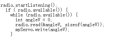
Similarly, you must set up your secondary Arduino as the receiver.
You’ll also note that a part includes the “angleV” variable in the code below.
It defines the angle of your servo motor’s rotation.
Primarily your circuit is now ready, and you can initiate wireless communication between the two Arduino modules.
Example 3 – Sending multiple variables in a single package
Lastly, our modules can send numerous variables using the above setup.
So, below are the transmitter and receiver codes.
Transmitter code

Receiver Code

Applications of NRF24L01 Modules
- RF remote control units.
- Telemetry
- Alarm systems
- Wireless mouse
- Home automation systems
Summary
With the NRF24L01 module, you can make as many Arduino wireless communication projects as possible.
Above, we have evaluated the key processes to undertake and the respective variations to the project you can make with the module.
All the best; try out your favorite NRF24L01 project, and always contact us for more.